AT89C5131A-S3SUM(2008) Ver la hoja de datos (PDF) - Atmel Corporation
Número de pieza
componentes Descripción
Fabricante
AT89C5131A-S3SUM Datasheet PDF : 188 Pages
| |||
5. Clock Controller
5.1 Introduction
The AT89C5130A/31A-M clock controller is based on an on-chip oscillator feeding an on-chip
Phase Lock Loop (PLL). All the internal clocks to the peripherals and CPU core are generated
by this controller.
The AT89C5130A/31A-M X1 and X2 pins are the input and the output of a single-stage on-chip
inverter (see Figure 5-1) that can be configured with off-chip components as a Pierce oscillator
(see Figure 5-2). Value of capacitors and crystal characteristics are detailed in the section “DC
Characteristics”.
The X1 pin can also be used as input for an external 48 MHz clock.
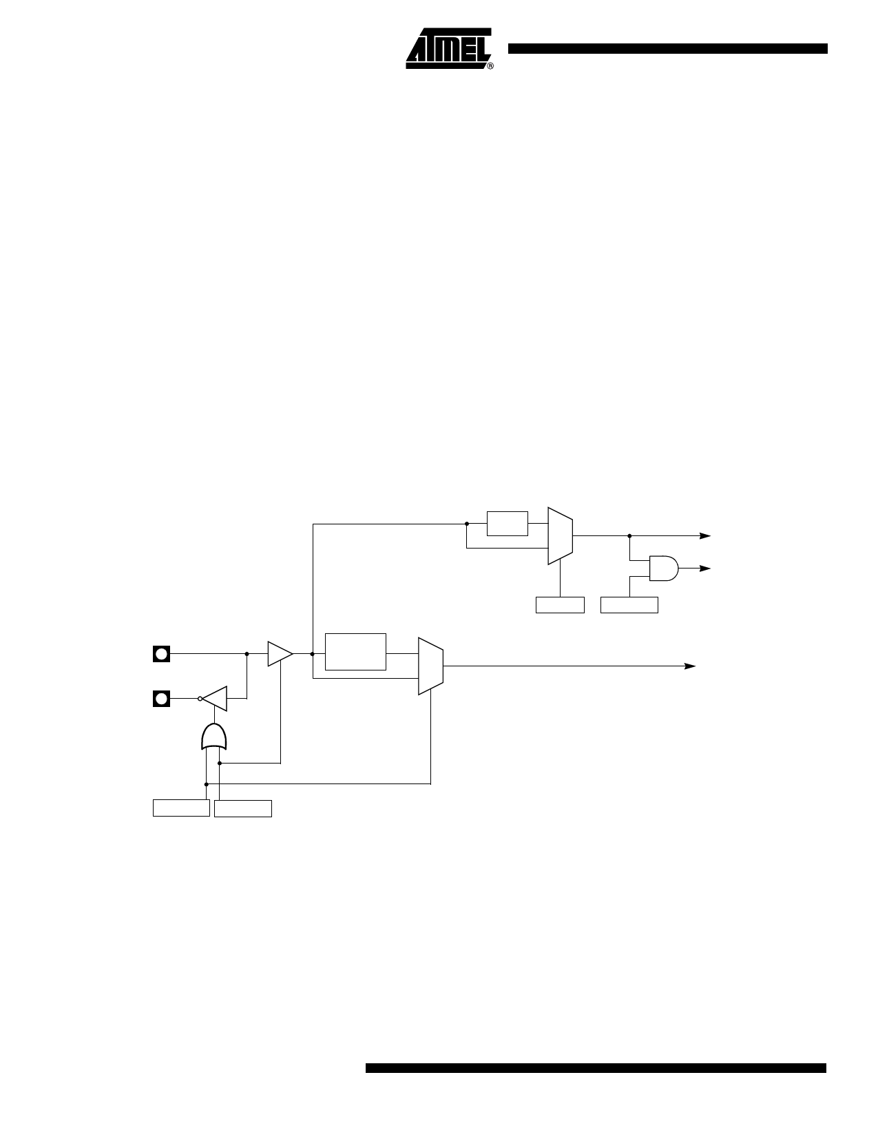
The clock controller outputs three different clocks as shown in Figure 5-1:
• a clock for the CPU core
• a clock for the peripherals which is used to generate the Timers, PCA, WD, and Port
sampling clocks
• a clock for the USB controller
These clocks are enabled or disabled depending on the power reduction mode as detailed in
Section “Power Management”, page 155.
Figure 5-1. Oscillator Block Diagram
÷2
0
1
Peripheral
Clock
CPU Core
Clock
X2
CKCON.0
IDL
PCON.0
X1
PLL
0
1
X2
USB
Clock
EXT48
PLLCON.2
PD
PCON.1
5.2 Oscillator
Two types of clock sources can be used for CPU:
• Crystal oscillator on X1 and X2 pins: Up to 32 MHz (Amplifier Bandwidth)
• External clock on X1 pin: Up to 48MHz
14 AT89C5130A/31A-M
4337K–USB–04/08
Share Link: 