MA1-B-34-615-1-A24-2-C Ver la hoja de datos (PDF) - Unspecified
Número de pieza
componentes Descripción
Fabricante
MA1-B-34-615-1-A24-2-C Datasheet PDF : 24 Pages
| |||
M-Series Circuit Breaker - Handle/Pushbutton UL Recognized - Ordering Scheme | 9
MM 1
1
Series
2
3
Actuator Poles
1 SERIES
M
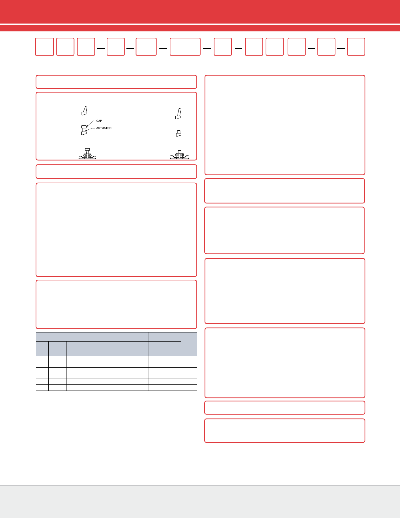
2 ACTUATOR 1
Handle
M
Paddle
Push Button
T
Push-Pull
Push Button with
Snap-In Mounting
V
Push-Pull
B
4
Circuit
34
5
Frequency
& Delay
260
6
Current
Rating
N
Baton
U
Push To Reset
W
Push To Reset
3 POLES
1
One
2
Two
4 CIRCUIT 2
without Auxiliary Switch
A
Switch Only (no coil), Maintained Contacts
B
Series Trip (Current)
with Auxiliary Switch, Silver Contacts Terminal Type:
M
Series Trip (Current) Aux Switch .110 QC x .020 QC
P 3 Switch Only, Maintained Contacts .060 Dia, Round Solder Turret
Q 3,4 Switch Only, Maintained Contacts .058 Dia, Round Q.C.
R 3,13 Switch Only, Maintained Contacts .080 Dia x .020 Flat Q.C.
S 3 Series Trip (Current)
.060 Dia, Round Solder Turret
T 3,4 Series Trip (Current)
.058 Dia, Round Q.C.
U 3,13 Series Trip, Maintained Contacts .080 Dia x .020 Flat Q.C.
with Auxiliary Switch, Gold Contacts
2 3,4 Switch Only, Maintained Contacts .058 Dia, Round Q.C.
3 3,13 Switch Only, Maintained Contacts .080 Dia x .020 Flat Q.C.
4 3,4 Series Trip (Current)
.058 Dia, Round Q.C.
5 3,13 Series Trip, Maintained Contacts .080 Dia x .020 Flat Q.C.
9
Series Trip (Current) Aux Switch .110 QC x .020 QC
5 FREQUENCY & DELAY
03 DC 50/60Hz, Switch Only
10 DC Instantaneous
12 DC Short
14 DC Medium
20 50/60Hz Instantaneous
22 50/60Hz Short
24 50/60Hz Medium
30 DC, 50/60Hz Instantaneous
32 DC, 50/60Hz Short
34 DC, 50/60Hz Medium
62 50/60Hz Short, Hi-Inrush
64 50/60Hz Medium, Hi-Inrush
72 DC, Short,Hi-Inrush
74 DC,Medium, Hi-Inrush
92 DC, 50/60Hz Short, Hi-Inrush
94 DC, 50/60Hz Medium, Hi-Inrush
Voltage
Full Load Amp
Rating
General Purpose Amps
Tungsten Lamp
Rating
Max
Rating
Frequency
Phase
Max
Amps
Choose
Current Coil
Rating Code
Max
Amps
Choose Current
Coil Rating Code
Max
Amps
Choose
Current Coil
Rating Code
Poles
Breaking
32
DC
- 15
615
25
625
-
-
1
50
DC
--
-
7.5 Consult Factory -
-
1
65
DC
1 15
615
25
625
-
-
2
125 50/60Hz 1 15
615
25
625
15
615
1
250 50/60Hz 1 12
612
-
-
-
1
250 50/60Hz 1 15
615
25
625
-
-
2
Notes:
1 One actuator is located in the center of each multi-pole breaker. Actuator codes V & W
limited to single pole breakers only.
2 Switch Only circuits are not available with Push-To-Reset actuators. For Switch Only circuits,
select Current Coil Rating from the above chart:
3 One Auxiliary Switch is supplied per breaker. On two-pole breakers, standard Auxiliary
Switch mounting is in pole one. Auxiliary Switch option limited to Series Trip and Switch Only
circuits. Not available with back connect screw or push-in stud terminals.
4 Mates with AMP .058” diameter pin receptacles including 60983-1 (gold plated)
and 60983-2 (tin plated).
5 Actuator color is only visible in the OFF position on Push-Pull actuators.
6 All units except snap-in mounting have one hex nut installed on bushing for use behind
the panel.
7 Other colors available. Consult factory.
8 TUV 20A, VDE 15A. UL Recognized and CSA Accepted to 30 amps.
Screw Terminals or Push-in Stud recommended above 20 amps.
9 30 amp rating not available with delay’s 30, 32, 34, 92 or 94.
10 Screw Terminals are VDE certified only with use of ring terminal attached to wire.
11 Terminal code A available with circuit codes A & B only.
12 Printed circuit board available with UL recognized approval only.
13 Auxiliary switch (flat Q.C.) available with UL recognized approvals only.
1
7
Terminal
1
8
Actuator
Color
BB
9
10
Front Panel Legend
Hardware Plate
C
11
Bushing
Color
B
12
Agency
Approval
6 CURRENT RATING (AMPERES)
CODE AMPERES
020 0.020
225 0.250
420 2.000
025 0.025
230 0.300
522 2.250
030 0.030
235 0.350
425 2.500
035 0.035
240 0.400
527 2.750
040 0.040
245 0.450
430 3.000
045 0.045
250 0.500
435 3.500
050 0.050
255 0.550
440 4.000
055 0.055
260 0.600
445 4.500
060 0.060
265 0.650
450 5.000
065 0.065
270 0.700
455 5.500
070 0.070
275 0.750
460 6.000
075 0.075
280 0.800
465 6.500
080 0.080
285 0.850
470 7.000
085 0.085
290 0.900
475 7.500
090 0.090
295 0.950
480 8.000
090 0.095
410 1.000
485 8.500
210 0.100
512 1.250
490 9.000
215 0.150
415 1.500
495 9.500
220 0.200
517 1.750
610 10.000
710 10.500
611 11.000
711 11.500
612 12.000
712 12.500
613 13.000
614 14.000
615 15.000
616 16.000
617 17.000
618 18.000
620 20.000
622 22.000
624 24.000
625
630
25.000
30.000
9
7 TERMINAL
1 Push-On 0.250 Tab (Q.C.)
2 10 Screw 8-32 with Upturned Lugs
3 10 Screw 8-32 (Bus Type)
A 11 Push-In Stud
P 12 Printed Circuit Board
8 ACTUATOR COLOR & LEGEND 5
Gloss Handle
Push-Button
1
A
2
B
3
C
4
D
5
E
6
F
8
H
Actuator Color
White
Black
Red
Green
Blue
Yellow
Orange
9 FRONT PANEL HARDWARE 6
Handle
No outer Panel Hardware
A
Knurled Nut
Bright nickel
B
Bright nickel with locking ring C
Black
D
Black with locking ring
E
Panel Dress Nut
Bright nickel
F
Bright nickel with locking ring G
Black
H
Black with locking ring
J
Push-Button
1
2
10 LEGEND PLATE / BUTTON MARKING
Handle Actuator Legend Plate (Actuator Styles M & N)
A
No Legend Plate
B
ON - OFF Vertical
C
ON - OFF Horizontal
D
I - O Vertical
E
I - O Horizontal
Push-Pull Actuator Button Cap (Actuator Styles T & V)
1
No Marking
2
Rated Amps Horizontal
3
Rated Amps Line Side Down
4
Rated Amps Line Side Up
Push-to-Reset Actuator Button (Actuator Styles U & W)
1
No Marking
11 BUSHING COLOR 7
B
Black
12 AGENCY APPROVAL 8
C
UL Recognized & CSA Accepted
D
VDE Certified, UL Recognized & CSA Accepted
E
TUV Certified, UL Recognized & CSA Accepted
Email: sales@carlingtech.com Application Support: team2@carlingtech.com
Phone: (860) 793–9281 Fax: (860) 793–9231 www.carlingtech.com
Share Link: 