ZXBM2004 Ver la hoja de datos (PDF) - Diodes Incorporated.
Número de pieza
componentes Descripción
Fabricante
ZXBM2004 Datasheet PDF : 19 Pages
| |||
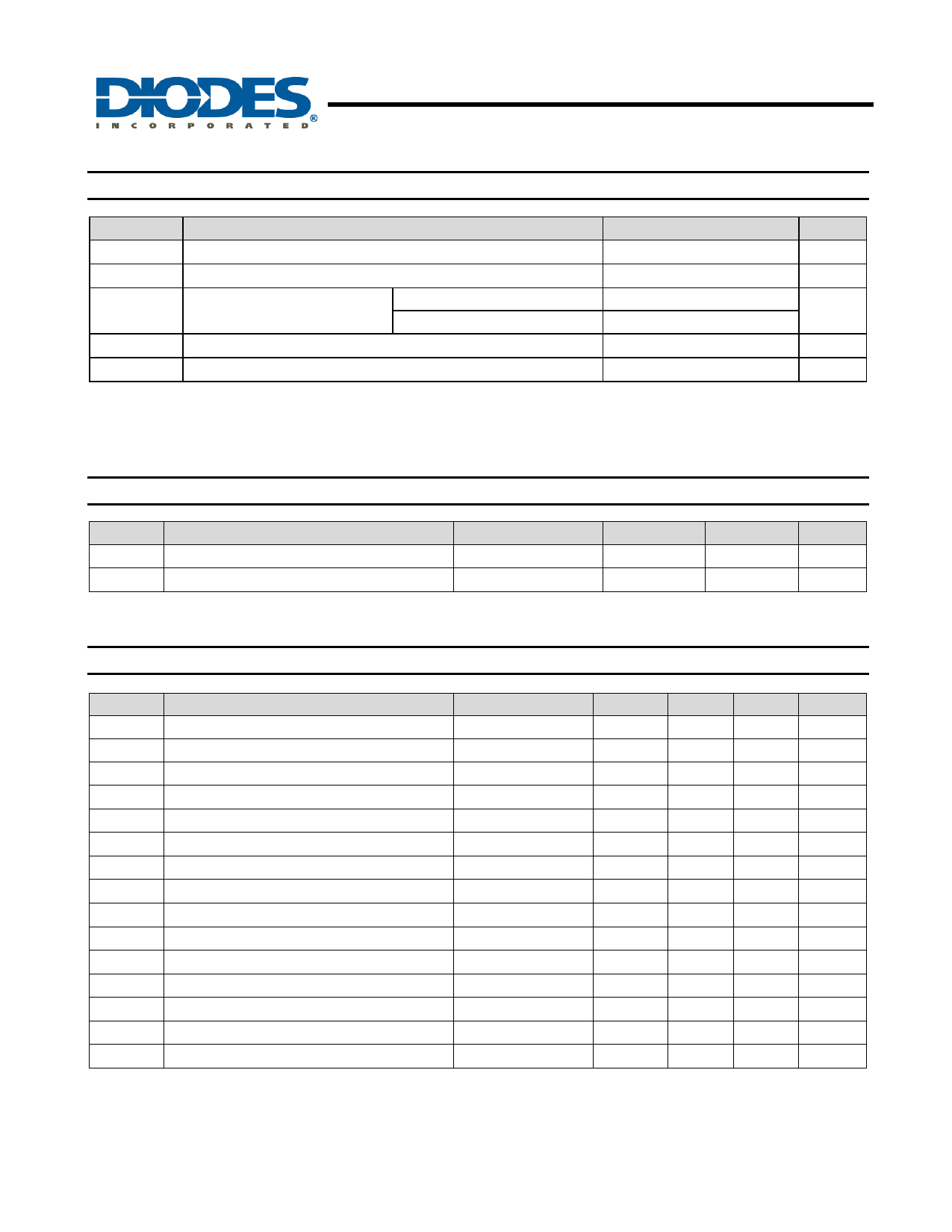
ZXBM2004
TWO PHASE VARIABLE SPEED
MOTOR CONTROL PRE-DRIVER
Absolute Maximum Ratings (TA = 25°C, unless otherwise noted, Note 2)
Symbol
Characteristics
Values
Unit
VCCMAX Supply voltage
-0.6 to +20
V
ICCMAX IC input current
100
mA
PDMAX
TA
TSTG
Power Dissipation (Note 4)
QSOP-16
U-QFN3030-16 (Note 3)
Operating ambient temperature
Storage Temperature Range
500
mW
1500
-40 to +110
oC
-55 to +150
oC
Note:
2. Stresses greater than the 'Absolute Maximum Ratings' specified above, may cause permanent damage to the device. These are stress ratings only;
functional operation of the device at these or any other conditions exceeding those indicated in this specification is not implied. Device reliability
may be affected by exposure to absolute maximum rating conditions for extended periods of time.
3. U-QFN3030-16 dissipation is based on a two-layer 2oz. copper 2”x 2” FR4 substrate PCB with thermal vias to the bottom layer.
Recommended Operating Conditions (TA = 25°C)
Symbol
VCC
TA
Parameter
Supply Voltage
Operating Temperature Range
Conditions
Operating
Operating
Min
Max
Unit
4.7
18.0
V
-40
+110
oC
Electrical Characteristics (TA = 25°C, VCC = 12V)
Symbol
Characteristics
Conditions
ICC Supply Current
VIN Hall amplifier input voltage
No Load (Note 4)
Diff peak to peak
VCM
VOFS
IBS
VOH
VOLA
VOLB
IOH
IOL
IPWMC
IPWMD
VTHH
VTHL
FPWM
Hall amplifier common mode voltage
Hall amplifier input offset voltage
Hall amplifier bias current
Ph1 and Ph2 output high voltage
Ph1 and Ph2 output low voltage
Ph1 and Ph2 output low voltage
Ph1 and Ph2 output source current
Ph1 and Ph2 output sink current
CPWM charge current
CPWM discharge current
CPWM high threshold voltage
CPWM low threshold voltage
PWM frequency
IOH = 80mA
IOH =16mA (Note 5)
IOH = 50uA (Note 6)
CPWM = 0.1nF
Notes:
4. Measure with pins H+, H-, CLCK and CPWM and all other signal pins open circuit
5. Measured when opposing Phase Output is Low
6. Measured when opposing Phase Output is High
Min
-
40
0.5
VCC -2.2
4.5
38
Typ.
Max
5.5
7.5
VCC -1.5
±7
400
700
Vcc -1.8
0.4
0.6
0.4
0.6
80
16
7.85
65
3
1
24
Unit
mA
mV
V
mV
nA
V
V
V
mA
mA
µA
µA
V
V
kHz
ZXBM2004
Document number: DS33433 Rev. 5 - 2
4 of 19
www.diodes.com
February 2012
© Diodes Incorporated
Share Link: 