L2422 Ver la hoja de datos (PDF) - Hamamatsu Photonics
Número de pieza
componentes Descripción
Fabricante
L2422 Datasheet PDF : 14 Pages
| |||
HANDLING PRECAUTIONS
HANDLING PRECAUTIONS
(Read before using)
Installation Precautions
1. Always handle the lamp with protective cover in
place.
High pressure gas (approx. 1 MPa at room temperature,
approx. 4 MPa during operation) is contained in the lamps.
Inflicting strong shocks to the lamp or scratching of the
surface of the glass bulb may cause the bulb to burst,
causing danger from flying glass fragments.
When handling lamps, always wear a long sleeved shirt
and gloves for protection as well as a face protector.
This protective cover is also necessary when replacing
lamps; so store it for future use. (Refer to item 8.)
2. Never touch the glass portion of a lamp with bare
hands.
Lighting a lamp with dust or fingerprints on it causes print
marks and loss of bulb transmittance, thus lowering the
light output and the mechanical strength of the glass bulb.
To remove dust and fingerprints, wipe the bulb off using
cotton or gauze moistened with high-quality alcohol or
acetone, and throughly wrung out. Use care not to apply
and strong shocks.
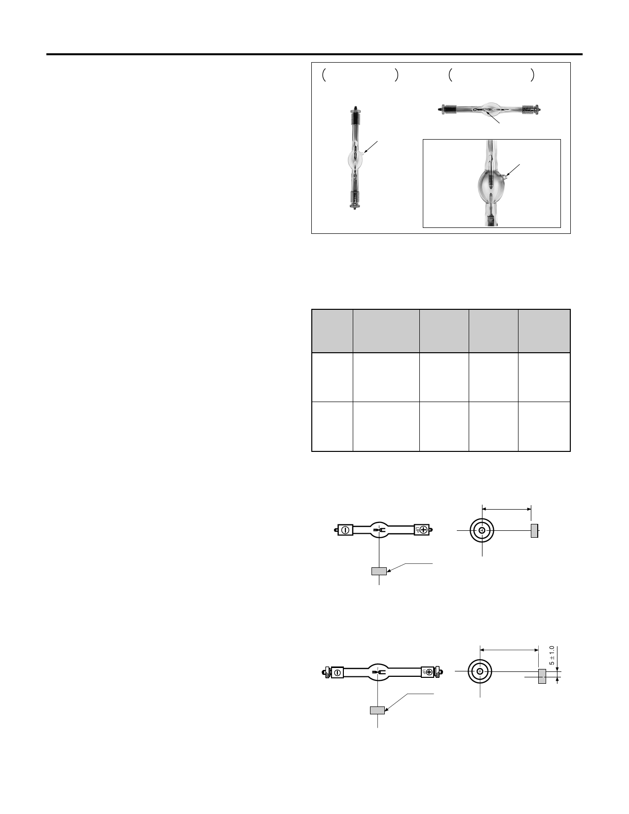
3. Install the lamp correctly.
(A) Correct polarity of the lamp is important. Even mo-
mentary reversal of the polarity will damage the cath-
ode, causing failure of the lamp and will void the war-
ranty. When installing the lamp vertical to the ground,
insure that the indication marking which denotes “UP”
is in the proper position. This indication marking can
be found on the anode side of the metal base, and
also on the plastic lamp protector.
(B) When installing the lamp in the horizontal position
make sure the “tip-off” is parallel to the ground. Ad-
just the arc point of the lamp so that the discharge
stays along the center line of both electrodes. This
can be accomplished by the use of a magnetic field.
ORIENTATION FOR
VERTICAL OPERATION
ANODE
(+)
TIP-OFF
CATHODE
(-)
ORIENTATION FOR
HORIZONTAL OPERATION
ANODE
(+)
CATHODE
(-)
TIP-OFF
TIP-OFF
It is necessary to use an adequate magnet and set it at correct
position in order to get the best performance of lamps, according
to the following table.
Type
Surface Magnetic Distance
Flux Density
(mm)
(10-3 Tesla)
Position
(Direction)
Magnet
Example
75 W
100 W
9.5 to 10.5
150 W
200 W
12 to 12.5
38±1.0
55±1.0
See Fig. 1
TDK Co.
FB3G
D10-5
(10 mm dia.
5 mm thickness)
See Fig. 2
TDK Co.
FB3G
D15-7
(15 mm dia.
7 mm thickness)
NOTE : “DISTANCE” in the table defines the distance between the center of arc
and the surface of a magnet.
Fig.1
(TOP VIEW)
38 ± 1.0
N
MAGNET
S
Fig.2
(TOP VIEW)
NS
(SIDE VIEW)
Unit: mm
TLSXC0011EA
55 ± 1.0
MAGNET
N
S
NS
(SIDE VIEW)
Unit: mm
TLSXC0012EA
10
Share Link: 