RNC50H1013FSR64 Ver la hoja de datos (PDF) - Vishay Semiconductors
Número de pieza
componentes Descripción
Fabricante
RNC50H1013FSR64
Vishay Semiconductors

RNC50H1013FSR64 Datasheet PDF : 4 Pages
| |||
www.vishay.com
ERC (Military RNC/RNR)
Vishay Dale
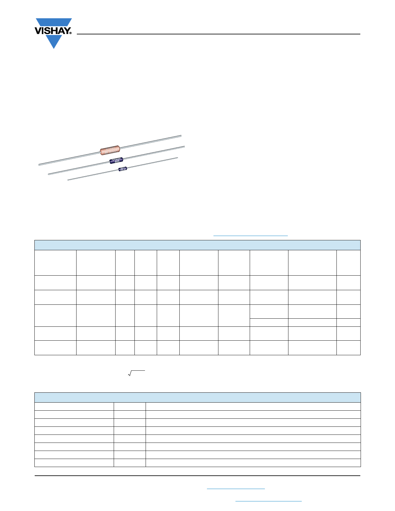
Metal Film Resistors, Axial, Military/Established Reliability,
MIL-PRF-55182 Qualified, Precision, Type RNC, Characteristics
J, H, K
FEATURES
• Meets requirements of MIL-PRF-55182
• Very low noise (-40 dB)
• Verified failure rate (contact factory for current level)
• 100 % stabilization and screening tests. Group A testing,
if desired, to customer requirements
• Controlled temperature coefficient
• Epoxy coating provides superior moisture protection
• Standard lead on RNC product is solderable and weldable
• Traceability of materials and processing
• Monthly acceptance testing
• Vishay Dale has complete capability to develop specific
reliability programs designed to customer requirements
• Extensive stocking program at distributors and factory on
RNC50, RNC55, RNC60 and RNC65
• For MIL-PRF-55182 characteristics E and C product, see
Vishay Angstrohm’s HDN (Military RNR/RNN) datasheet
(www.vishay.com/doc?66001)
STANDARD ELECTRICAL SPECIFICATIONS
GLOBAL
MODEL
MIL-PRF-55182
STYLE
MIL
SPEC.
SHEET
POWER
RATING
P70 °C
W
POWER
RATING
P125 °C
W
TOLERANCE (4)
±%
MAXIMUM
WORKING
VOLTAGE (2)
V
RESISTANCE
RANGE
TEMPERATURE LIFE
COEFFICIENT FAILURE
± ppm/°C
RATE (1)
ERC50,
ERC50..31 (3)
RNC50, RNR50 07
0.10
0.05
0.1, 0.5, 1
200
10 to 796K
100 (K), 50 (H), 25 (J)
M, P,
R, S
ERC55,
ERC55..65 (3)
RNC55, RNR55 01
0.125
0.10
0.1, 0.5, 1
200
10 to 2M
100 (K), 50 (H), 25 (J)
M, P,
R, S
ERC55..200,
ERC55..201 (3)
RNC60, RNR60
03
ERC65,
ERC65..65 (3)
RNC65, RNR65 05
0.25 0.125
0.50 0.25
0.1, 0.5, 1
0.1, 0.5, 1
250
10 to 2M
100 (K), 50 (H), 25 (J)
M, P,
R, S
2.01M to 3.01M 100 (K), 50 (H), 25 (J) M
300
10 to 3.01M
100 (K), 50 (H), 25 (J)
M, P,
R
ERC70
ERC70..4 (3)
RNC70, RNR70 06
0.75 0.50
0.1, 0.5, 1
350
10 to 3.01M
100 (K), 50 (H), 25 (J)
M, P,
R
Notes
(1) Consult factory for current QPL failure rates.
(2) Continuous working voltage shall be P x R or maximum working voltage, whichever is less.
(3) Hot solder dipped leads.
(4) Tolerance of ± 0.1 % is not applicable to characteristics K.
TECHNICAL SPECIFICATIONS
PARAMETER
UNIT
Voltage Coefficient, max.
ppm/V
Dielectric Strength
VAC
Insulations Resistance
Operating Temperature Range
°C
Terminal Strength
lb
Solderability
Weight
g
CONDITION
5/V when measured between 10 % and full rated voltage
RNC50, RNC55 and RNC60 = 450; RNC65 and RNC70 = 900
1011 dry; 109 after moisture test
-65 to +175
2 lb pull test on RNC50, RNC55, RNC60 and RNC65; 4.5 lb pull test on RNC70
Continuous satisfactory coverage when tested in accordance with MIL-STD-202, method 208
RNC50 = 0.11; RNC55 = 0.35; RNC60 = 0.35; RNC65 = 0.84; RNC70 = 1.06
Revision: 16-Sep-16
1
Document Number: 31025
For technical questions, contact: ff2aresistors@vishay.com
THIS DOCUMENT IS SUBJECT TO CHANGE WITHOUT NOTICE. THE PRODUCTS DESCRIBED HEREIN AND THIS DOCUMENT
ARE SUBJECT TO SPECIFIC DISCLAIMERS, SET FORTH AT www.vishay.com/doc?91000
Share Link: