LR645 Ver la hoja de datos (PDF) - Supertex Inc
Número de pieza
componentes Descripción
Fabricante
LR645 Datasheet PDF : 9 Pages
| |||
LR645
LR645: High Current SMPS Start-Up Circuit
The 8 lead version of the LR645 has connections for an ex-
ternal depletion-mode MOSFET for higher output current and
external resistors for adjustable output voltage. As shown in
Figure 2, the output current is increased to 150mA by using
the Supertex 400V depletion-mode MOSFET DN2540. The
maximum operating input voltage will be limited by the drain-
to-source breakdown voltage of the external MOSFET, but
cannot exceed the 450V rating of the LR645.
The output voltage can be adjusted from 8V to 12V with 2ex-
ternal resistors, R1 and R2. The ratio of R2/R1 determines
the output voltage. R2 is connected between the VOUT and
TRIM pins. R1 is connected between TRIM and GND pins.
Figure 5 is a curve showing output voltage versus resistor
ratio R2/R1. The optimum range for R1 + R2 is 200KΩ to
300KΩ. This minimizes loading and optimizes accuracy of
the output voltage. Figure 5 uses an R1 + R2 of 250KΩ.
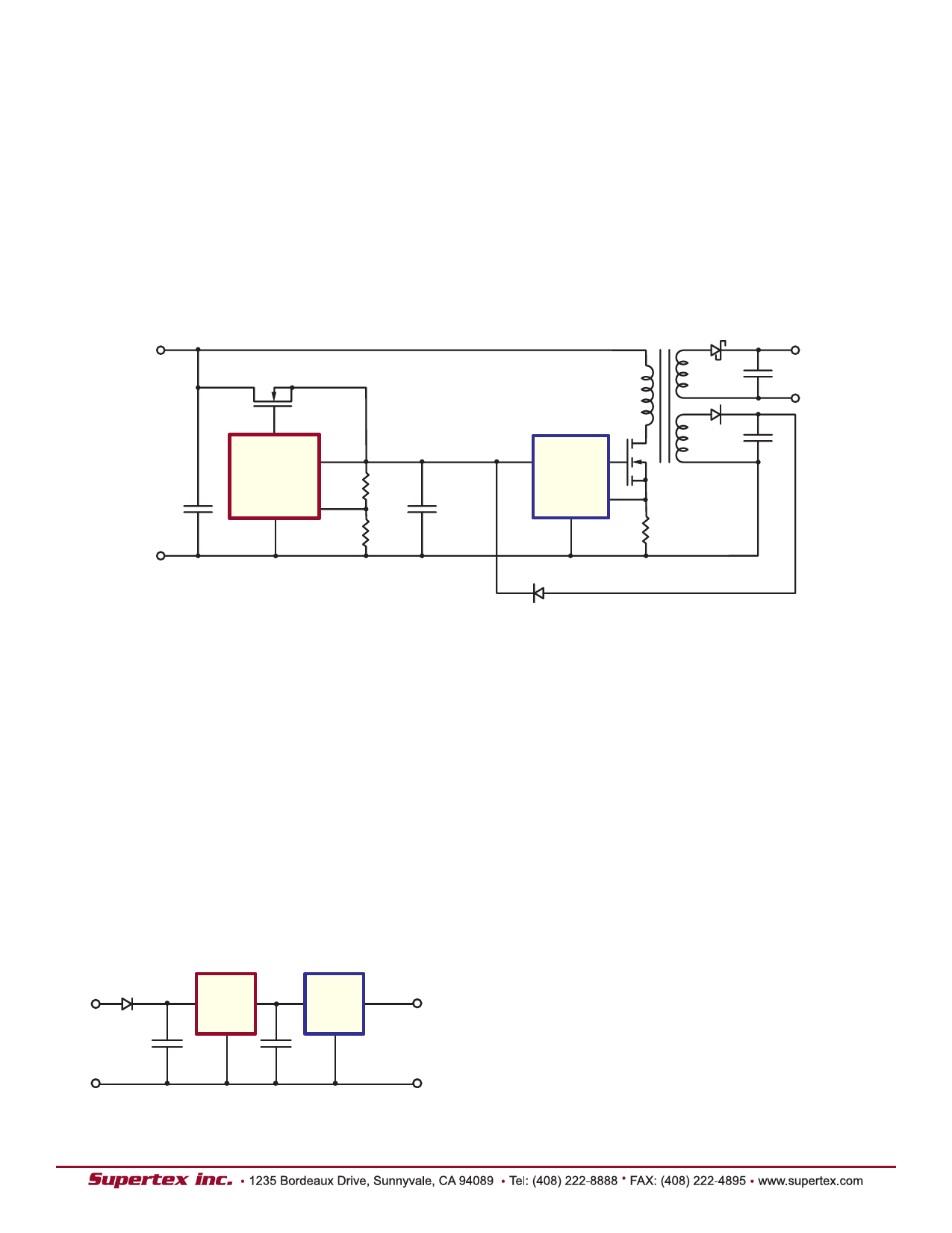
Figure 2: High Current SMPS Start-Up Circuit
+
DN2540
15V
to
400V
CIN
–
GATE
LR645
VOUT
R2
TRIM
GND
R1
COUT
Note: When used with the DN25, +VIN is not connected on the LR6.
VCC
PWM IC
+
5.0V
–
VAUX = 12V
LR645: Off Line Linear Regulator
Circuits requiring low voltages to operate logic and analog
circuits benefit from the LR645. The conventional use of
step down transformers can be eliminated, thereby saving
space and cost. Some examples of these applications are:
proximity controlled light switches, street lamp controls, and
low voltage power supplies for appliances such as washing
machines, dishwashers, and refrigerators.
The wide operating input voltage range of 15V to 450V as
well as the ripple rejection ratio of 50dB minimum allows the
use of a small, high voltage input capacitor. The input AC
line can be either full-wave or half-wave rectified. A minimum
output capacitance of 0.01µF is recommended for output
stability.
Figure 3: Cascading for Precision
Figure 3 shows the LR645 as a pre-regulator to a precision-
regulator for high precision regulation. Higher output cur-
rent is also possible by using an external depletion-mode
MOSFET DN2540N5 as shown in Figure 4.
Power Dissipation Considerations
The LR645 is a true linear regulator. Its power dissipation is-
therefore a function of input voltage and output load current.
Forexample, if the LR645 is providing a continuous load cur-
rent of 3mAat 10V while its input voltage is 400V, total dis-
sipation in the LR645 will be:
PDISS= (VIN - VOUT) x (IOUT + IMAX ) QUIESCENT
= (400V - 10V) x (3.0mA + 150µA)
= 1.23 Watts
AC Line
24V
to
277V
LR6
CIN
1.0µF
Max
875
ACSA
COUT
0.1µF
5.000V
± 0.002V
@
0 to 3mA
The 1.23 watts is for continuous operation. This is within the
dissipation capabilities of the TO-220 and SOT-89 packag-
es. See the thermal characteristics chart on page 2 for derat-
ings. For SMPS start-up applications, the output current is
usually required only during start-up. This duration depends
upon the auxiliary supply output capacitor and COUT, but is
typically a few hundred milliseconds. All package types of
the LR645 have been characterized for use with a COUT of at
least 10µF, and an AC line of 277V.
4
Share Link: 