MAX1838 Ver la hoja de datos (PDF) - Maxim Integrated
Número de pieza
componentes Descripción
Fabricante
MAX1838 Datasheet PDF : 12 Pages
| |||
Dual USB Switch with Fault Blanking
and Autoreset
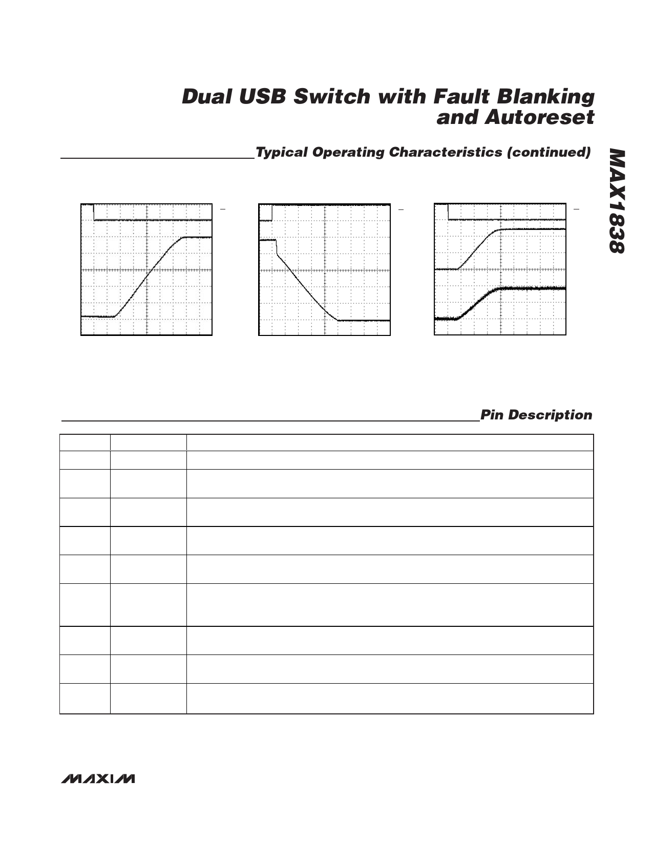
Typical Operating Characteristics (continued)
(Circuit of Figure 2, VIN_ = 5V, TA = +25°C, unless otherwise noted.)
SWITCH TURN-ON TIME, COUT = 1µF
MAX1838 toc17
5V
VON
0
SWITCH TURN-OFF TIME,
COUT = 1µF ROUT = 10Ω
MAX1838 toc18
5V
VON
0
START-UP TIME INTO 10Ω LOAD
MAX1838 toc19
5V
VON
0
5V
5V
4V
VOUT_
4V
4V
2V
3V
VOUT_
2V
3V
0
VOUT_
2V
0.5A
1V
1V
IOUT_
0
0
0
1ms/div
1ms/div
1ms/div
Pin Description
PIN
1, 8
2
3, 6
4, 5
7
9
10
11, 12
13, 14
NAME
GND
SEL
AUXA, AUXB
INA, INB
ON
FAULTB
ADJB
OUTB1, OUTB2
OUTA1, OUTA2
FUNCTION
Ground. Connect both GND pins together.
Select Input. Control input to select from either VIN_ or VAUX_ for both outputs. Pull SEL high for
power from IN source, low for power from AUX source.
Auxiliary Input. Connect both AUX pins together and bypass with a 0.1µF capacitor to ground.
Load conditions may require additional bulk capacitance to maintain AUX voltage regulation.
Power Input. Connect both IN pins together and bypass with a 0.1µF capacitor to GND. Load
conditions may require additional bulk capacitance to maintain the IN voltage regulation.
Control Input. A logic low at ON turns on the device. A logic high shuts off both outputs and all
power to internal circuits. Driving ON higher than IN does not cause damage.
Fault Indicator Output for Channel B. This open-drain output goes low when channel B is in
thermal shutdown or in undervoltage lockout or in a sustained (>20ms) current-limit or short-circuit
condition.
Current-Limit Adjust for Channel B. When operating from auxiliary input, adjust the current limit by
connecting a resistor from ADJB to GND as shown in Programmable Current Limit.
Power Output B. Connect both OUTB_ pins together. Connect a 1µF or greater capacitor from
OUTB_ to ground. Load condition may require additional bulk capacitance.
Power Output A. Connect both OUTA_ pins together. Connect a 1µF or greater capacitor from
OUTA_ to ground. Load condition may require additional bulk capacitance.
_______________________________________________________________________________________ 7
Share Link: 