NMT0572SC Ver la hoja de datos (PDF) - Murata Manufacturing
Número de pieza
componentes Descripción
Fabricante
NMT0572SC Datasheet PDF : 4 Pages
| |||
NMT Series
Triple Output 3W DC/DC Converters
APPLICATION NOTES
RIPPLE SPECIFICATION
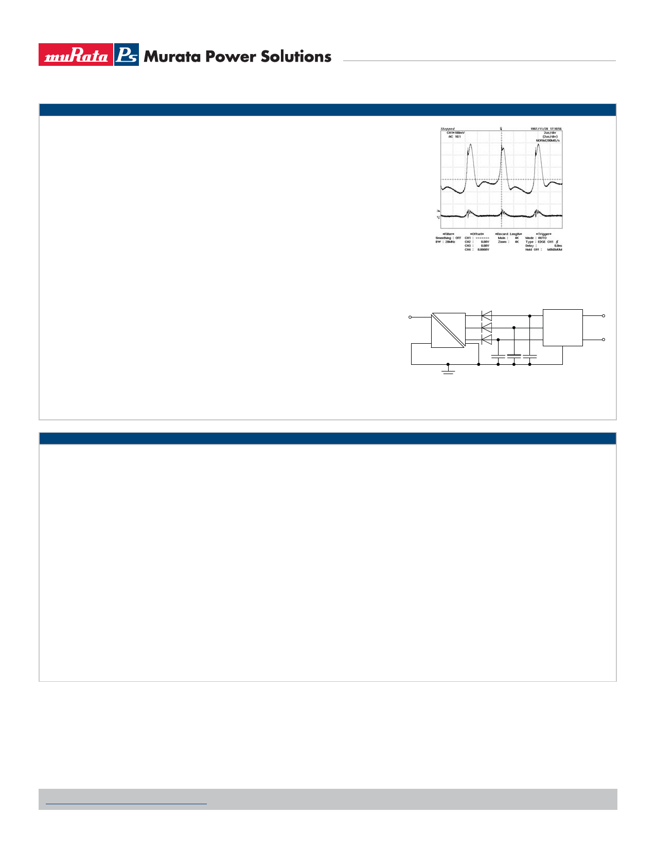
The output ripple for the NMT series is higher than standard for a Murata Power Solutions DC/DC converter.
This is due to using low value ceramic capacitors internally for longer life perfomance of the component and
the superimposition of ripples between each output channel. Consequently with a maximum 400mV ripple per
output channel, at -72V the ripple is potentially three times this value (1.2V). The ripple will always be additively
superimposed since the output windings are synchronized.
To reduce ripple, external capacitors are recommended with a value of 1μF per channel (see figure 1). This
typically reduces the ripple to 50mV per channel. Further ripple reduction can be achieved by use of series
inductors on each output channel plus additional external capacitors to form a pi-filter with the internal capaci-
tors of the device.
SLIC CIRCUITS
The primary application for the NMT series is in subscriber line interface circuits (SLIC’s), particularly for the
Integrated Services Digital Network (ISDN). The NMT can also be used in standard telecommunications circuits
where a local power source is preferred to the telephone system power due to either the power quality of the
Figure 1. VOUT3 Output Ripple
Top: No external capacitors
Bottom: 1μF per channel external capacitors
telecommunications system power supply or to avoid potential power line disturbances, such as lightening
strikes and access switching, which will effect the target circuit function.
Another application area is in fibre-in-the-loop (FITL) or radio-in-the-loop (RITL) interfacing via a standard tele-
communication SLIC, where the usual telecommunication battery voltage is not available due to the transmis-
sion media in use (fibre or radio). In particular, FITL/RITL interfaces directly on PC cards, in local monitor and
boost circuits and at exchanges between the fibre/radio and wire media.
7*/
7*/
/.54$
7065 7
%$ 7065 7
%$
7065 7
07
".% "N3
7#"5
"
7#"5
7/&(
#
#(/%
5*1
3*/(
The supply rails can be used for ringing generators as well as SLIC circuits or where both are combined, such as
in the AMD AM79R79 Ringing SLIC device (see figure 2). The -72V rail is used primarily for the generation of the
ringing signal (VBAT1), the -48V rail is used to supply in line access circuitry (VBAT2) and the -24V supply for the
on-chip regulator for the logic interface (VNEG). Alternative devices from other manufacturers could use the -24V
output for their internal circuit supply and -72V for ringing.
Figure 2. Supply for Ringing SLIC Device
TECHNICAL NOTES
ISOLATION VOLTAGE
‘Hi Pot Test’, ‘Flash Tested’, ‘Withstand Voltage’, ‘Proof Voltage’, ‘Dielectric Withstand Voltage’ & ‘Isolation Test Voltage’ are all terms that relate to the same thing, a test voltage,
applied for a specified time, across a component designed to provide electrical isolation, to verify the integrity of that isolation.
Murata Power Solutions NMT series of DC/DC converters are all 100% production tested at their stated isolation voltage. This is 1kVDC for 1 second.
A question commonly asked is, “What is the continuous voltage that can be applied across the part in normal operation?”
For a part holding no specific agency approvals, such as the NMT series, both input and output should normally be maintained within SELV limits i.e. less than 42.4V peak, or
60VDC. The isolation test voltage represents a measure of immunity to transient voltages and the part should never be used as an element of a safety isolation system. The part
could be expected to function correctly with several hundred volts offset applied continuously across the isolation barrier; but then the circuitry on both sides of the barrier must
be regarded as operating at an unsafe voltage and further isolation/insulation systems must form a barrier between these circuits and any user-accessible circuitry according to
safety standard requirements.
REPEATED HIGH-VOLTAGE ISOLATION TESTING
It is well known that repeated high-voltage isolation testing of a barrier component can actually degrade isolation capability, to a lesser or greater degree depending on materials,
construction and environment. The NMT series has toroidal isolation transformers, with no additional insulation between primary and secondary windings of enameled wire. While
parts can be expected to withstand several times the stated test voltage, the isolation capability does depend on the wire insulation. Any material, including this enamel (typically
polyurethane) is susceptible to eventual chemical degradation when subject to very high applied voltages thus implying that the number of tests should be strictly limited. We
therefore strongly advise against repeated high voltage isolation testing, but if it is absolutely required, that the voltage be reduced by 20% from specified test voltage.
This consideration equally applies to agency recognized parts rated for better than functional isolation where the wire enamel insulation is always supplemented by a further
insulation system of physical spacing or barriers.
www.murata-ps.com/support
KDC_NMT.E04 Page 3 of 4
Share Link: 