NTE3095 Ver la hoja de datos (PDF) - NTE Electronics
Número de pieza
componentes Descripción
Fabricante
NTE3095 Datasheet PDF : 4 Pages
| |||
Switching Characteristics: (TA = +25°C, VCC = 5V, IF = 16mA unless otherwise specified)
Parameter
Symbol
Test Conditions
Min Typ Max Unit
Propagation Delay Time to Logic
Low at Output (Each Channel)
tpHL RL = 1.9kΩ
– 0.2 0.8 µs
Propagation Delay Time to Logic
High at Output (Each Channel)
tpLH RL = 1.9kΩ
– 0.3 0.8 µs
Common Mode Transient Immunity
at Logic High Level Output
(Each Channel)
CMH
IF = 0mA, VCM = 400VP–P,
RL = 1.9kΩ, Note 7
– 1000 – V/µs
Common Mode Transient Immunity
at Logic Low Level Output
(Each Channel)
CML
IF = 16mA, VCM = 400VP–P,
RL = 1.9kΩ, Note 7
– –1000 – V/µs
Bandwidth (Each Channel)
BW RL = 100Ω, Note 8
–
2
– MHz
Note 7. Common mode transient immunity in Logic High level is the maximum tolerable (positive)
dVcm/dt on the leading edge of the common mode pulse, Vcm, to assure that the output will
remain in a Logic High state (i.e., VO > 2V). Common mode transient immunity in Logic Low
level is the maximum tolerable (negative) dVcm/dt on the trailing edge of the common mode
pulse signal, Vcm, to assure that the output will remain in a Logic Low state (i.e., VO > 0.8V).
Note 8. The frequency at which the AC output voltage is 3dB below the low frequency asymptote.
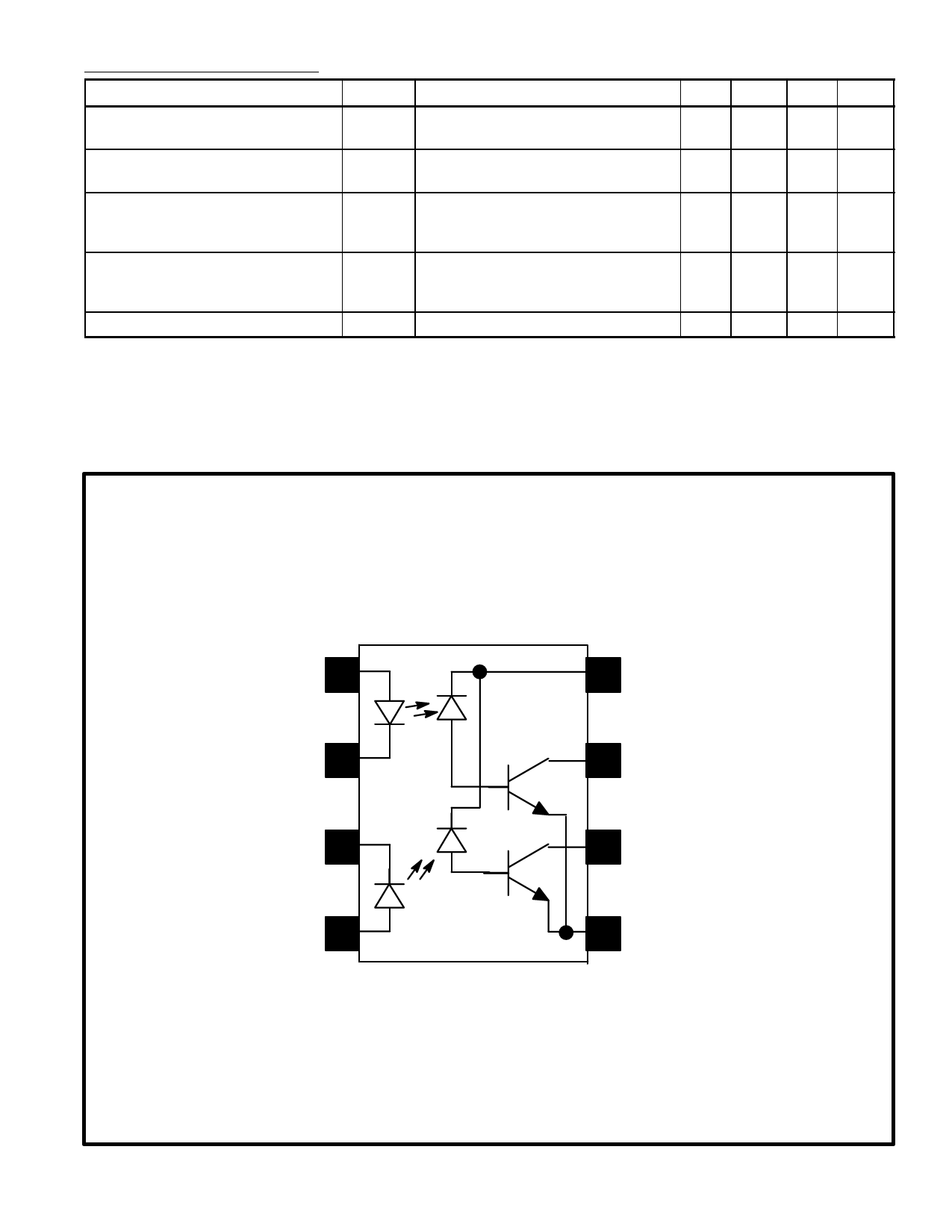
Pin Connection Diagram
Anode 1 1
Cathode 1 2
Cathode 2 3
Anode 2 4
8 VCC
7 VO1
6 VO2
5 GND
Share Link: 