MX613 Ver la hoja de datos (PDF) - CML Microsystems Plc
Número de pieza
componentes Descripción
Fabricante
MX613 Datasheet PDF : 10 Pages
| |||
Global Call Progress Tone Detector
6
Application Information ......
Decoder Timing
MX613 Preliminary Information
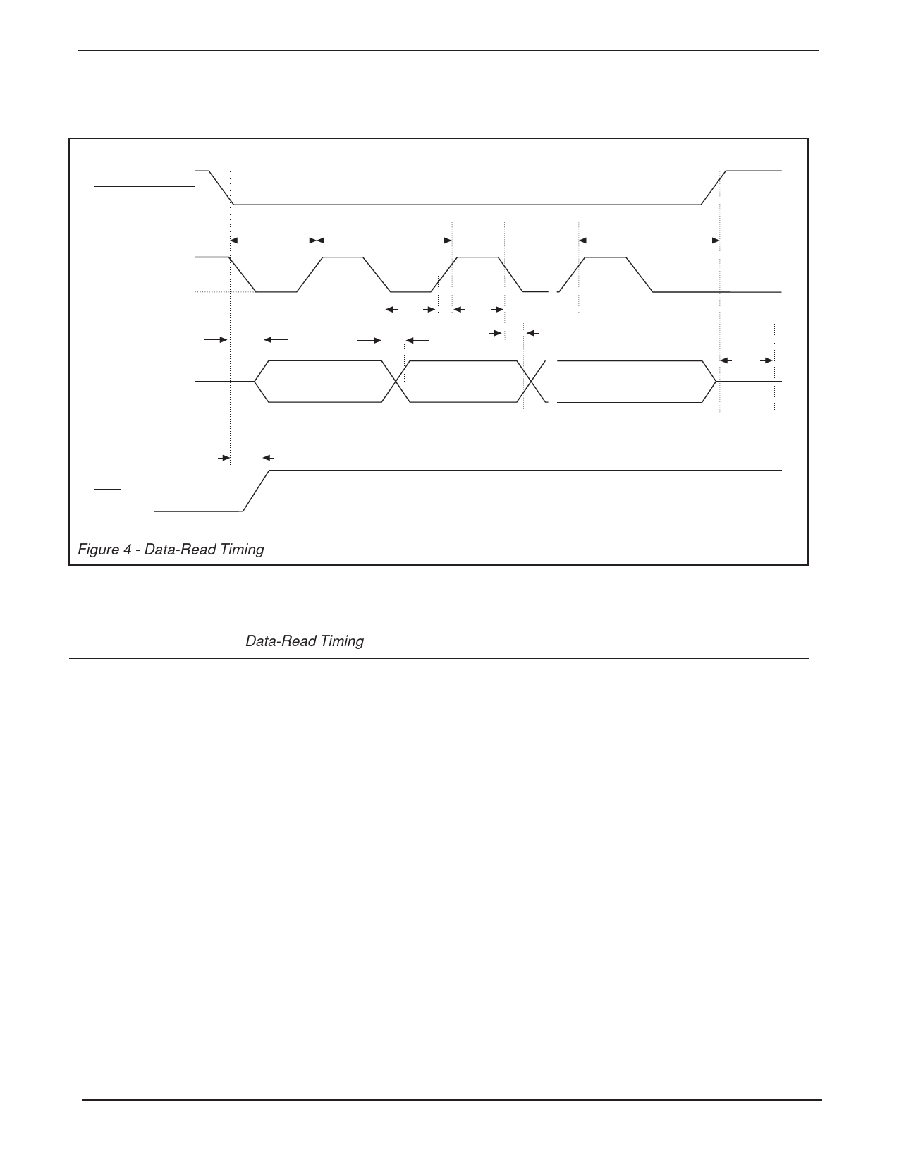
CHIP SELECT
tCSE
tCYC
tCSH
SERIAL CLOCK
tDE
tPWL
tPWH
tCDS
tDH
DATA OUT
TRI-STATE
BIT 5
BIT 4
tHIZ
BIT 0
tIR
IRQ
Figure 4 - Data-Read Timing
Decoder Timing Characteristics
With reference to Figure 4, Data-Read Timing.
Characteristics
Min.
Typ.
Max.
Unit
tPWH
Serial Clock “High” Pulse Width
250
tPWL
Serial Clock “Low” Pulse Width
250
tCYC
Serial Clock-Cycle Time
600
tCSE
Chip Select Low to Clock “High” Edge
450
tCSH
Last Clock “High” Edge to CS “High”
600
tDH
Data Out Hold Time
0
t
Clock Edge to Data Out Set Time
-
CDS
tIR
Interrupt (IRQ) Reset Time
-
tDE
Chip Select “Low” to Data Enable
-
tHIZ
Chip Select “High” to Output Tri-State
-
-
-
ns
-
-
ns
-
-
ns
-
-
ns
-
-
ns
-
-
ns
-
200
ns
-
200
ns
-
200
ns
-
1000
ns
Notes
1 Data is output bit 5 first. Bit 5 can be clocked into the µProcessor by the first Serial Clock rising edge.
If 8 Serial Clock pulses are employed the last 2 data-bits will be “0” and should be ignored by the software.
2 Chip Select should be used to react to Interrupts and then returned to a logic “1”.
If Chip Select stays low there will be no further Interrupts and no Data Output update.
© 1997 MX•COM Inc.
www.mxcom.com Tele: 800 638-5577 910 744-5050 Fax: 910 744-5054
Doc. # 20480086.003
4800 Bethania Station Road, Winston-Salem, NC 27105-1201 USAAll trademarks and service marks are held by their respective companies
Share Link: 