CS51021 Ver la hoja de datos (PDF) - Cherry semiconductor
Número de pieza
componentes Descripción
Fabricante
CS51021 Datasheet PDF : 9 Pages
| |||
Circuit Description: continued
input of the PWM comparator is a combination of these
dVSLOPE
two voltages. The slope compensation, dt , is calcu-
lated using the following formula:
dVSLOPE
dt
=
0.1
×
53µA
CS
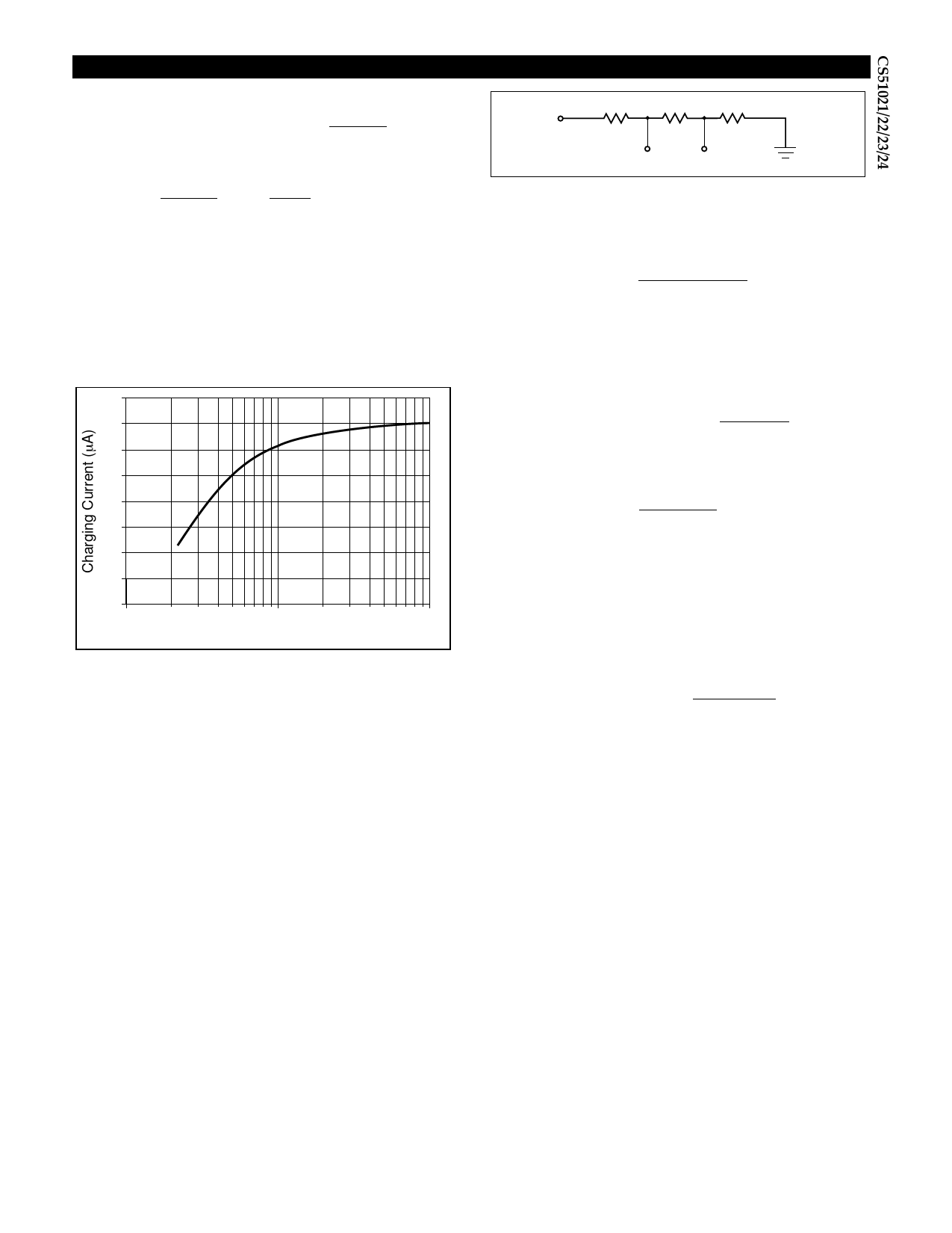
It should be noted that internal capacitance of the IC will
cause an error when determining slope compensation
capacitance CS. This error is typically small for large val-
ues of CS, but increases as CS becomes small and compara-
ble to the internal capacitance. The effect is apparent as a
reduction in charging current due to the need to charge
the internal capacitance in parallel with CS. Figure 3 shows
a typical curve indicating this decrease in available charg-
ing current.
60
55
50
45
40
35
30
25
VIN
R1
R2
R3
VUV
VOV
Figure 4: UV/OV Monitor Divider
To calculate the OV/UV resistor divider:
1. Solve for R3, based on OV hysteresis requirements.
R3 =
VOV(HYST) × 2.5V
VMAX × 12.5µA
’
where VOV(HYST) is the desired amount of overvoltage hys-
teresis, and VMAX is the input voltage at which the supply
will shut down.
2. Find the total impedance of the divider.
RTOT = R1 + R2 + R3 =
VMAX × R3
2.5
3. Determine the value of R2 from the UV threshold condi-
tions.
R2 =
1.45 × RTOT
VMIN
− R3,
where VMIN is the UV voltage at which the supply will
shut down.
20
10
100
1000
Compensation Cap (pF)
Figure 3: The slope compensation pin charge current reduces when a
small capacitor is used.
Undervoltage (UV) and Overvoltage (OV) Monitor
Two independent comparators monitor OV and UV con-
ditions. A string of three resistors is connected in series
between the monitored voltage (usually the input voltage)
and ground (see Figure 4). When voltage at the OV pin
exceeds 2.5V, an overvoltage condition is detected and
GATE shuts down. An internal 12.5µA current source
turns on and feeds current into the external resistor, R3,
creating a hysteresis determined by the value of this resis-
tor (the higher the value, the greater the hysteresis). The
hysteresis voltage of the OV monitor is determined by the
following formula:
VOV(HYST) = 12.5µA × R3
where R3 is a resistor connected from the OV pin to ground.
When the monitored voltage is low and the UV pin is less
than 1.45V, GATE shuts down. The UV pin has fixed 75mV
hysteresis.
Both OV and UV conditions are latched until the Soft Start
capacitor is discharged. This way, every time a fault con-
dition is detected the controller goes through the power
up sequence.
4. Calculate R1.
R1 = RTOT − R2 − R3
5. The undervoltage hysteresis is given by:
VUV(HYST) =
VMIN × 0.075
1.45
Synchronization
A bi-directional synchronization is provided to synchro-
nize several controllers. When SYNC pins are connected
together, the converters will lock to the highest switching
frequency. The fastest controller becomes the master, pro-
ducing a 4.3V, 200ns pulse train. Only one, the highest fre-
quency SYNC signal, will appear on the SYNC line.
Sleep
The sleep input is an active high input. The CS51022/51024
is placed in sleep mode when SLEEP is driven high. In
sleep mode, the controller and MOSFET are turned off.
Connect to Gnd for normal operation. The sleep mode
operates at VCC ≤ 15V.
Oscillator and Duty Cycle Limit
The switching frequency is set by RT and CT connected to
the RTCT pin. CT charges and discharges between 3V and
1.5V.
The maximum duty cycle is set by the ratio of the on time,
tON, and the whole period, T = tON + tOFF. Because the
7
Share Link: 