ML6509CS Ver la hoja de datos (PDF) - Micro Linear Corporation
Número de pieza
componentes Descripción
Fabricante
ML6509CS Datasheet PDF : 10 Pages
| |||
ML6509
FUNCTIONAL DESCRIPTION
The SCSI terminator helps in decreasing the transmission
line effects with precise termination. Termination is
conventionally provided at the beginning and end of the
SCSI bus, however when additional peripherals are added,
the termination needs to be disabled from the current
device and enabled on the last device on the bus. Existing
termination schemes use a SIP (Single-In-Line package)
which is plugged into a socket on the PC board of the
SCSI peripheral. To remove the termination, the user
needs to pull the resistor SIP out of its socket. With the
higher levels of system integration, this is no longer a
simple task. With the increasing use of higher data rates
and cable lengths in SCSI subsystems, the need for active
termination is becoming necessary. Active termination
also minimizes power dissipation and can be activated or
deactivated under software control, thus eliminating the
need for end user intervention. The V-I characteristics of
popular SCSI termination schemes are shown in Figure 3.
Theoretically the desired V-I characteristics are the Boulay
type for signal assertion (high to low) and the Ideal type
for signal negation. The ML6509 with its MOSFET based
nonlinear termination element attempts to provide the
most optimum V-I characteristics — optimized for both
signal assertion and negation.
The ML6509 provides active termination for nine signal
lines, thus accommodating basic SCSI which requires 18
lines to be terminated and wide SCSI which requires 27,
36 or 45 lines to be terminated. The ML6509 integrates an
accurate voltage reference (1V dropout voltage) and nine
MOSFET based termination lines. A single internal resistor
is trimmed to tune the V-I characteristic of the MOSFETs as
shown in figure 1. The voltage reference circuit produces
a precise 2.85V level and is capable of sourcing at least
24mA into each of the nine terminating lines when low
(active). When the signal line is negated (driver turns off),
the terminator pulls the signal line to 2.85V (quiescent
state). When all signal lines are inactive, the regulator will
source about 200mA.
The ML6509 SCSI Terminator provides two control
signals, DISCNKT & LPWR which are active low signals
and have an internal 200ký pull-up resistor. The
DISCNKT input when asserted low, isolates the ML6509
from the signal lines and effectively removes the
terminator from the SCSI bus with a disconnect mode
current of less than 100µA. The LPWR input, when
asserted low, puts the ML6509 in the low power
termination mode by providing only a 1mA drive
capability with an effective termination impedance of
2.5kW. This is intended for power conscious portable
systems and peripheral applications where the cable
lengths are small, thus resulting is fast signal transitions
and practically no transmission line effects, while
consuming minimum power (9mA worst case if all lines
were active). At the same time, if this portable system
were connected with an external SCSI peripheral, over a
long cable, the normal terminator mode could be enabled
to ensure compliance with the SCSI standard and maintain
data integrity. In addition the ML6509 provides for
negative clamping of signal transients and also supports
current sink capability in excess of 10mA per signal line
to handle active negation driver overshoot above 2.85V,
a common occurrence with SCSI transceivers. These
functions need to be handled with external components
in SCSI subsystems today. Thus the ML6509 helps in
eliminating a number of external components.
Disconnect mode capacitance is a very critical parameter
in SCSI systems. The ML6509 provides the lowest
capacitance contribution of maximum 5pF which is
guaranteed by production test.
Figure 2 gives an application diagram showing a typical
SCSI bus configuration. To ensure proper operation, the
TERMPWR pin must be connected to the SCSI
TERMPWR line. Each ML6509 requires parallel 0.1µF and
10µF capacitors connected between VREF and GND pins
and the TERMPWR line needs a 10µF bypass capacitor
per SCSI system.
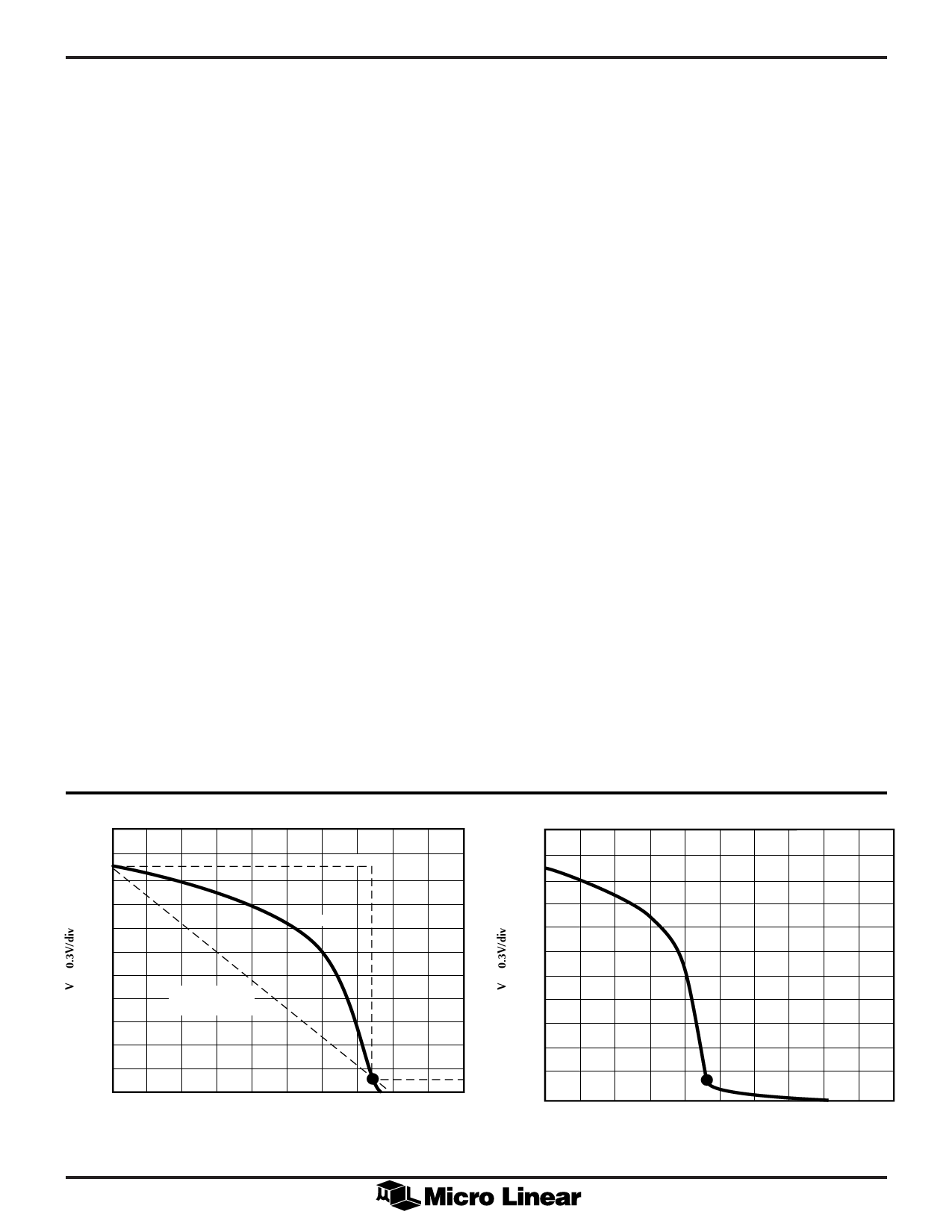
3.0V
2.844V
NORMAL TERMINATION MODE
IDEAL
3.00V
2.85V
LOWPOWER TERMINATION MODE
ML6509
BOULAY
(SLOPE = 110Ω)
0
4
22.4mA
30.0mA
0
IL 3.00mA/div
1mA
IL 0.2mA/div
2mA
Figure 1. Trimmed V-I Characteristic of the ML6509
Share Link: 