LTC1642IGN Ver la hoja de datos (PDF) - Linear Technology
Número de pieza
componentes Descripción
Fabricante
LTC1642IGN Datasheet PDF : 16 Pages
| |||
LTC1642
DC ELECTRICAL CHARACTERISTICS
The ● denotes the specifications which apply over the full operating temperature range, otherwise specifications are at TA = 25°C.
VCC = 5V unless otherwise specified.
SYMBOL PARAMETER
CONDITIONS
MIN TYP MAX UNITS
ICR
CRWBR Pin Current
CRWBR On, VCRWBR = 0V
CRWBR On, VCRWBR = 2.1V
CRWBR Off, VCRWBR = 1.5V
● – 30 – 45 – 60
µA
● –1000 –1500
µA
2.3
mA
VCB
Circuit Breaker Trip Voltage
VCB = (VCC – VSENSE), VFB = GND
● 15
25
36
mV
VCB = (VCC – VSENSE), VFB = 1V
● 45
52.5
60
mV
2.97V ≤ VCC ≤ 16.5V,
VCB = (VCC – VSENSE), VFB = GND
● 12
25
39
mV
VCB = (VCC – VSENSE), VFB = 1V
● 42
52.5
63
mV
ISENSE
SENSE Pin Input Bias Current
VCC = VSENSE = 16.5V
●
0.5
µA
IGATE
GATE Pin Output Current
Charge Pump On, VGATE = GND
Charge Pump Off, VGATE = 5V
● – 20 – 25 – 30
µA
10
mA
∆VGATE
External N-Channel Gate Drive
VGATE – VCC, VCC = 2.97V
VGATE – VCC, VCC = 5V
VGATE – VCC, VCC = 15V
● 4.5
5.9
8.0
V
● 10
11.5
14
V
● 4.5
8.5
18
V
VONHI
ON Pin Threshold
ON Rising
1.30 1.34 1.38
V
VONLO
ON Pin Threshold
ON Falling
● 1.20 1.22 1.26
V
VONHYST ON Pin Hysteresis
110
mV
ION(IN)
ON Pin Input Current
VON = 5V
●
0
±1
µA
VOL
Output Low Voltage
RESET, FAULT, COMPOUT IOL = 1.54mA ●
RESET, FAULT IO = 5mA
0.4
V
2
V
IPU
Logic Output Pull-Up Current
RESET, FAULT = GND
– 15
µA
VREF
Reference Output Voltage
No Load
● 1.208 1.220 1.232
V
∆VLNR
Reference Supply Variation
2.97V ≤ VCC ≤ 16.5V, No Load
●
5
15
mV
∆VLDR
Reference Load Regulation
IO = 0mA to –1mA, Sourcing Only
●
2.5
7.5
mV
IRSC
Reference Short-Circuit Current
VREF = 0V
4.5
mA
VCOS
Comparator Offset Voltage
VCM = VREF
●
±10
mV
VCHYST
Comparator Hysteresis
VCM = VREF
3
mV
Note 1: Absolute Maximum Ratings are those values beyond which the life of a device may be impaired.
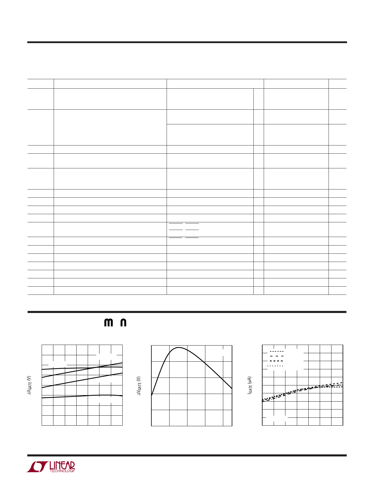
TYPICAL PERFOR A CE CHARACTERISTICS
∆VGATE vs Temperature
16
14
12
VCC = 5V
VCC = 12V
10
VCC = 15V
8
6
VCC = 3V
4
2
0
–50 –25
0 25 50 75
TEMPERATURE (°C)
100 125
1642 G03
∆VGATE vs VCC
15
12
TA = 25°C
9
6
3
0
3
6
9
12
15
VCC (V)
1642 G26
IGATE vs Temperature
30
29
VCC = 3V
VCC = 5V
28
VCC = 12V
27
VCC = 15V
26
25
24
23
22
21 VGATE = 0V
20
–50 –25 0 25 50 75
TEMPERATURE (°C)
100 125
1642 G04
1642fb
3
Share Link: 