EL4585CN Ver la hoja de datos (PDF) - Elantec -> Intersil
Número de pieza
componentes Descripción
Fabricante
EL4585CN Datasheet PDF : 16 Pages
| |||
EL4585C
Horizontal Genlock 8 FSC
Choosing Loop Filter
Components
The PLL VCO and loop filter can be described
as
4585 – 13
Where
Kdephase detector gain in A rad
F(s)eloop filter impedance in V A
KVCOeVCO gain in rad s V
NeTotal internal or external divisor (see 3 be-
low)
It can be shown that for the loop filter shown
below
C3
e
KdKVCO
N0n2
C4
e
C3
10
R3
e
2Ng0n
KdKVCO
Where 0neloop filter bandwidth and geloop
filter damping factor
1 Kd e 300mA 2qrad e 4 77e-5A rad for the
EL4585C
2 The loop bandwidth should be about H-sync
frequency 20 and the damping ratio should be
1 for optimum performance For our example
0ne15 734kHz 20e787 Hz 5000 rad S
3 N e 910x2 e 1820 from table 1
N e FVCO e 28 636M e 1820 e 910x2
FHsync 15 73426k
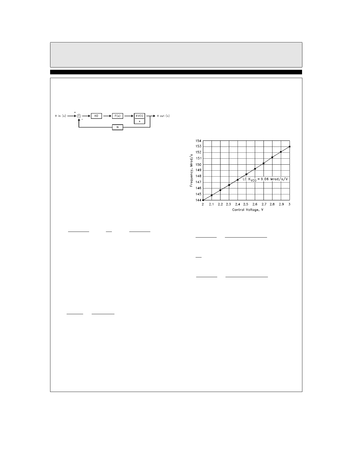
4 KVCO represents how much the VCO frequen-
cy changes for each volt applied at the control
pin It is assumed (but probably isn’t) linear
about the lock point (2 5V) Its value depends
on the VCO configuration and the varactor
transfer function CveF(VC) where VC is the re-
verse bias control voltage and CV is varactor ca-
pacitance Since F(VC) is nonlinear it is probably
best to build the VCO and measure KVCO about
2 5V The results of one such measurement are
shown below The slope of the curve is deter-
mined by linear regression techniques and equals
KVCO For our example KVCOe9 06 Mrad s V
FOSC vs VC LC VCO
5 Now we can solve for C3 C4 and R3
4585 – 14
C3
e
KdKVCO
N0n2
e
(4 77eb5)(9 06e6)
(1820)(5000)2
e
0
01mF
C4
e
C3
10
e
0
001mF
R3
e
2Ng0n
KdKVCO
e
(2)(1820)(1)(5000)
(4 77eb5)(9 06e6)
e
42
1kX
We choose R3e43kX for convenience
6 Notice R2 has little effect on the loop filter de-
sign R2 should be large around 100k and can
be adjusted to compensate for any static phase
error Ti at lock but if made too large will
slow loop response If R2 is made smaller Ti
(see timing diagrams) increases and if R2 in-
10
Share Link: 