RS2051(2010) Ver la hoja de datos (PDF) - Orister Corporation
Número de pieza
componentes Descripción
Fabricante
RS2051 Datasheet PDF : 11 Pages
| |||
Page No. : 6/11
Internal Synchronized Slope Compensation
Although there are more advantages of the current mode control than conventional voltage mode control, there are still several
drawbacks of peak-sensing current-mode converter, especially the open loop instability when it operates in higher than 50% of
the duty-cycle. To solve this problem, the RS2051 is introduced an internal slope compensation adding voltage ramp to the
current sense input voltage for PWM generation. It improves the close loop stability greatly at CCM, prevents the sub-harmonic
oscillation and thus reduces the output ripple voltage.
VSLOP
= 0.33 × DUTY
DUTYMAX
= 0.4389 × DUTY
Slope Compensation
Current Sensing & Dynamic peak limiting
The current flowing by the power MOSFET comes into being a voltage VSENSE on the Sense pin cycle-by-cycle, which compares
to the internal reference voltage, and controls the reverse of the internal register, limits the peak current IMAX of the primary of
the transformer. The transformer energy is
E
=
1
2
×
L
×
IMAX 2
.
So
adjusting
the
RSENSE
can
set
the
maximal
output
power
of
the power supple. The current flowing by the power MOSFET
has an extra
value
( ΔI =
VIN
LP
× TD ) due
to
the system delay time
that is from detecting the current through the Sense pin to power MOSFET off in the RS2051 (Among these, VIN is the primary
winding voltage of the transformer and LP is the primary wind inductance). VIN ranges from 85VAC to 264VAC. To guarantee the
output power is a constant for universal input AC voltage, there is a dynamic peak limit circuit to compensate the system delay T
that the system delay brings on.
Vsense
1.10
1.05
1.00
0.95
0.90
0.85
0.80
0.75
0.70
0.65
Duty Cycle
0% 10%20%30%40%50%60%70%80%90%
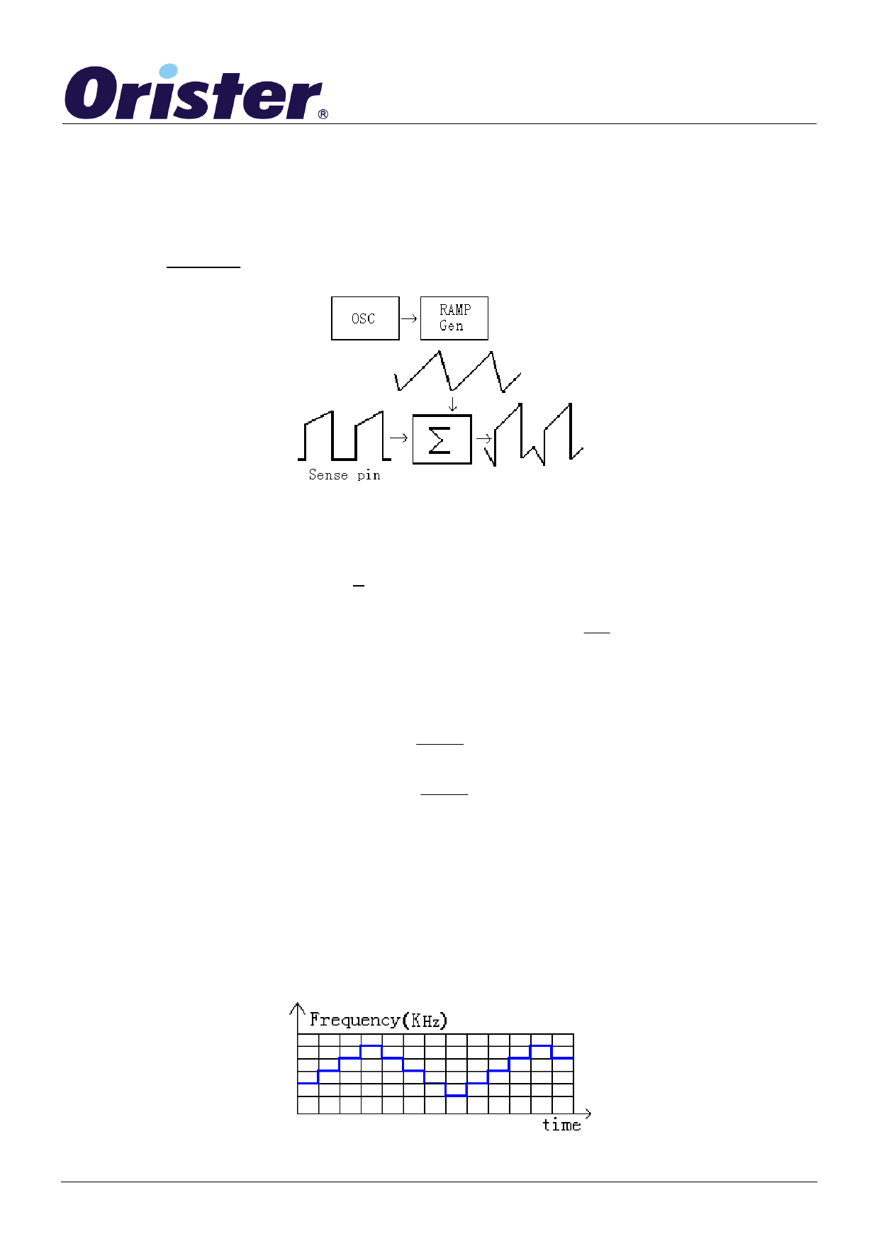
Frequency Jiggling for EMI improvement
The Frequency Jiggling Technique is introduced in the RS2051. As following figure, the internal oscillation frequency is
modulated by itself. A whole surge cycle includes 128 pulses and the Jiggling ranges from -4% to +4%. Thus, the function could
minimize the electromagnetic interferer from the power supply module.
Frequency(HZ)
70K
65K
DS-RS2051-09 No v, 2010
60K
Time
Frequency Jiggling for EMI
www.Orister.com
Share Link: 