IHB60S2403C Ver la hoja de datos (PDF) - Murata Power Solutions
Número de pieza
componentes Descripción
Fabricante
IHB60S2403C Datasheet PDF : 4 Pages
| |||
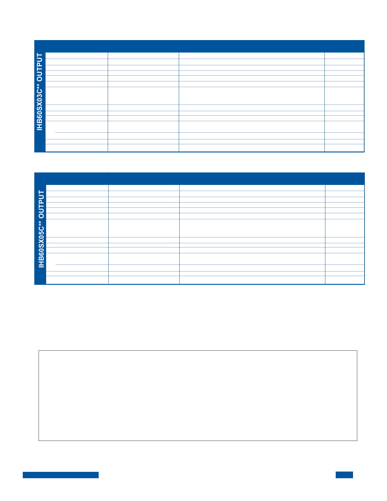
SPECIFICATIONS, ALL MODELS
Specifications are at T = +40°C nominal input voltage unless otherwise specified.
CASE
PARAMETER
Output Power
Set Point Voltage
Output Current, IOUT
Output Ripple, p-p
Output Adjust Range
Output Temperature Drift
Line Regulation
CONDITIONS
60 Watts Max
IO Nom
DC to 20MHz*
*
VIN, Min≤VIN≤VIN, Max
Min
Nom
30
3.3
0
9.0
100
3.15
.02
Load Regulation
Current Limit Inception
Short-Circuit Current
Transient Response
Peak Deviation
Settling Time
Overvoltage Limit
Efficiency
IO = IO, Nom
Min Load to Rated Load
Other Outputs Min Load
50 to 100% Load Step
VOUT, 1% of VOUT, Nom
VIN=NOM, IO=18A
0.05
0.50
23
19
150
35
4.2
83
84
PARAMETER
Output Power
Set Point Voltage
Output Current, IOUT
Output Ripple, p-p
Output Adjust Range
Output Temperature Drift
Line Regulation
CONDITIONS
60 Watts Max
I
O Nom
DC to 20MHz*
*
VIN, Min≤VIN≤VIN, Max
Load Regulation
Current Limit Inception
Short-Circuit Current
Transient Response
Peak Deviation
Settling Time
Overvoltage Limit
Efficiency
IO = IO, Nom
Min Load to Rated Load
50 to 100% Load Step
VOUT, 1% of VOUT, Nom
VIN=NOM, IO=12A
*See Application Notes available on the web at www.murata-ps.com
**X = Either 24 or 48
VOUT
Min
Nom
30
5.1
0
6.0
100
4.60
.02
0.05
0.50
16.0
12.6
200
35
6.0
86
87
VOUT
Max
60
18.0
200
3.80
.05
0.10
1.00
25
250
50
5.0
Max
60
12
200
5.50
.05
0.10
1.0
16.0
300
50
6.8
UNITS
W
V
A
mV
V
%/°C
%
%
A
A
mV
MSec
V
%
UNITS
W
V
A
mV
V
%/°C
%
%
A
A
mV
MSec
V
%
THROUGH-HOLE SOLDERING INFORMATION
These devices are intended for wave soldering or manual soldering.
They are not intended to be subject to surface mount processes under any circumstances.
The normal wave soldering process can be used with these devices where the device is subjected
to a maximum wave temperature of 260°C for a period of no more than 10 seconds. Within this
time and temperature range, the integrity of the device’s plastic body will not be compromised and
internal temperatures within the converter will not exceed 175°C. Care should be taken to control
manual soldering limits identical to that of wave soldering.
IHB60SC REV A (RoHS) 04/2006
3
Share Link: 