APT40M42JN Ver la hoja de datos (PDF) - Advanced Power Technology
Nû¤mero de pieza
componentes Descripciû°n
Fabricante
APT40M42JN Datasheet PDF : 4 Pages
| |||
DYNAMIC CHARACTERISTICS
Symbol
Ciss
Coss
Crss
Qg
Qgs
Qgd
td(on)
tr
td(off)
tf
Characteristic
Input Capacitance
Output Capacitance
Reverse Transfer Capacitance
Total Gate Charge 3
Gate-Source Charge
Gate-Drain ("Miller ") Charge
Turn-on Delay Time
Rise Time
Turn-off Delay Time
Fall Time
Test Conditions
VGS = 0V
VDS = 25V
f = 1 MHz
VGS = 10V
VDD = 0.5 VDSS
ID = ID [Cont.] @ 25ô¯C
VGS = 15V
VDD = 0.5 VDSS
ID = ID [Cont.] @ 25ô¯C
RG = 0.6ãÎ
APT40M42JN
MIN TYP MAX UNIT
11140 14000
2600 3640 pF
960 1440
507 760
70 105 nC
234 350
21
40
41
80
ns
62
95
14
30
SOURCE-DRAIN DIODE RATINGS AND CHARACTERISTICS
Symbol Characteristic / Test Conditions
IS
Continuous Source Current
(Body Diode)
MIN
APT40M42JN
ISM
Pulsed Source Current 1
(Body Diode)
APT40M42JN
VSD Diode Forward Voltage 2 (VGS = 0V, IS = -ID [Cont.])
t rr
Reverse Recovery Time (IS = -ID [Cont.], dlS/dt = 100A/ôçs)
Q rr Reverse Recovery Charge (IS = -ID [Cont.], dlS/dt = 100A/ôçs)
TYP MAX UNIT
86
Amps
344
1.8 Volts
535 1070 ns
13
26
ôçC
PACKAGE CHARACTERISTICS
Symbol Characteristic / Test Conditions
MIN TYP MAX
LD
Internal Drain Inductance (Measured From Drain Terminal to Center of Die.)
3
LS
Internal Source Inductance (Measured From Source Terminals to Source Bond Pads)
5
VIsolation RMS Voltage (50-60 Hz Sinusoidal Waveform From Terminals to Mounting Base for 1 Min.) 2500
CIsolation Drain-to-Mounting Base Capacitance (f = 1MHz)
70
Torque Maximum Torque for Device Mounting Screws and Electrical Terminations.
13
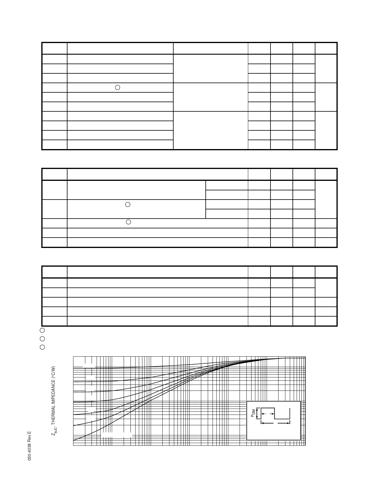
1 Repetitive Rating: Pulse width limited by maximum junction temperature. See Transient Thermal Impedance Curve. (Fig.1)
2 Pulse Test: Pulse width < 380 ôçS, Duty Cycle < 2%
3 See MIL-STD-750 Method 3471
0.2
0.1
D=0.5
0.05
0.2
0.1
0.01
0.005
0.001
0.05
0.02
0.01
SINGLE PULSE
Note:
t1
t2
Duty Factor D = t1/t2
Peak TJ = PDM x Zö¡JC + TC
0.0005
10-5
10-4
10-3
10-2
10-1
1.0
10
RECTANGULAR PULSE DURATION (SECONDS)
FIGURE 1, MAXIMUM EFFECTIVE TRANSIENT THERMAL IMPEDANCE, JUNCTION-TO-CASE vs PULSE DURATION
UNIT
nH
Volts
pF
in-lbs
Share Link: 