TMP01GBC Ver la hoja de datos (PDF) - Analog Devices
Número de pieza
componentes Descripción
Fabricante
TMP01GBC Datasheet PDF : 16 Pages
| |||
TMP01
Switching Loads With The Open-Collector Outputs
In many temperature sensing and control applications some type
of switching is required. Whether it be to turn on a heater when
the temperature goes below a minimum value or to turn off a
motor that is overheating, the open-collector outputs Over and
Under can be used. For the majority of applications, the switches
used need to handle large currents on the order of 1 amp and
above. Because the TMP01 is accurately measuring tempera-
ture, the open-collector outputs should handle less than 20 mA
of current to minimize self-heating. Clearly, the Over-temp and
Under-temp outputs should not drive the equipment directly.
Instead, an external switching device is required to handle the
large currents. Some examples of these are relays, power
MOSFETs, thyristors, IGBTs, and Darlingtons.
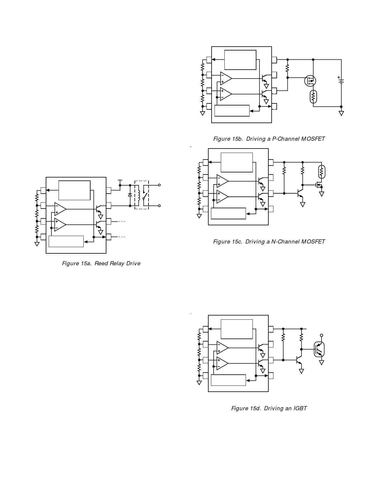
Figure 15 shows a variety of circuits where the TMP01 controls
a switch. The main consideration in these circuits, such as the
relay in Figure 15a, is the current required to activate the
switch.
+12V
1
VREF
TEMPERATURE
SENSOR &
VOLTAGE
VPTAT
8
IN4001
R1
REFERENCE
OR EQUIV.
MOTOR
SHUTDOWN
2
7
R2
WINDOW
COMPARATOR
3
6
2604-12-311
COTO
R3
4
HYSTERESIS
5
GENERATOR
TMP01
Figure 15a. Reed Relay Drive
It is important to check the particular relay you choose to ensure
that the current needed to activate the coil does not exceed the
TMP01’s recommended output current of 20 mA. This is easily
determined by dividing the relay coil voltage by the specified
coil resistance. Keep in mind that the inductance of the relay
will create large voltage spikes that can damage the TMP01 out-
put unless protected by a commutation diode across the coil, as
shown. The relay shown has a contact rating of 10 watts maxi-
mum. If a relay capable of handling more power is desired, the
larger contacts will probably require a commensurately larger
coil, with lower coil resistance and thus higher trigger current.
As the contact power handling capability increases, so does the
current needed for the coil. In some cases an external driving
transistor should be used to remove the current load on the
TMP01 as explained in the next section.
Power FETs are popular for handling a variety of high current
DC loads. Figure 15b shows the TMP01 driving a p-channel
MOSFET transistor for a simple heater circuit. When the out-
put transistor turns on, the gate of the MOSFET is pulled down
to approximately 0.6 V, turning it on. For most MOSFETs a
gate-to-source voltage or Vgs on the order of –2 V to –5 V is suf-
ficient to turn the device on. Figure 15c shows a similar circuit
for turning on an n-channel MOSFET, except that now the gate
to source voltage is positive. Because of this reason an external
transistor must be used as an inverter so that the MOSFET will
turn on when the “Under Temp” output pulls down.
R1
VREF
1
TEMPERATURE
SENSOR &
VOLTAGE
VPTAT
8
V+
REFERENCE
2.4kΩ (12V)
1.2kΩ (6V)
2
7 NC 5%
IRFR9024
R2
WINDOW
OR EQUIV.
COMPARATOR
3
6
R3
HEATING
ELEMENT
4
HYSTERESIS
5 NC
GENERATOR
TMP01
NC = NO CONNECT
Figure 15b. Driving a P-Channel MOSFET
VREF
1
TEMPERATURE
SENSOR &
VPTAT
VOLTAGE
8
V+
R1
REFERENCE
4.7kΩ 4.7kΩ
2
7 NC
HEATING
ELEMENT
R2
WINDOW
COMPARATOR
3
6
2N1711
IRF130
R3
4
HYSTERESIS
5 NC
GENERATOR
TMP01
NC = NO CONNECT
Figure 15c. Driving a N-Channel MOSFET
Isolated Gate Bipolar Transistors (IGBT) combine many of the
benefits of power MOSFETs with bipolar transistors, and are
used for a variety of high power applications. Because IGBTs
have a gate similar to MOSFETs, turning on and off the devices
is relatively simple as shown in Figure 15d. The turn on voltage
for the IGBT shown (IRGBC40S) is between 3.0 and 5.5 volts.
This part has a continuous collector current rating of 50 A and a
maximum collector to emitter voltage of 600 V, enabling it to
work in very demanding applications.
VREF
1
TEMPERATURE
SENSOR &
VOLTAGE
VPTAT
8
V+
R1
REFERENCE
4.7kΩ 4.7kΩ
2
7 NC
R2
WINDOW
COMPARATOR
3
6
2N1711
R3
4
HYSTERESIS
5 NC
GENERATOR
TMP01
NC = NO CONNECT
Figure 15d. Driving an IGBT
MOTOR
CONTROL
IRGBC40S
–10–
REV. C
Share Link: 