TA3020 Ver la hoja de datos (PDF) - Tripath Technology Inc.
Número de pieza
componentes Descripción
Fabricante
TA3020
Tripath Technology Inc.

TA3020 Datasheet PDF : 29 Pages
| |||
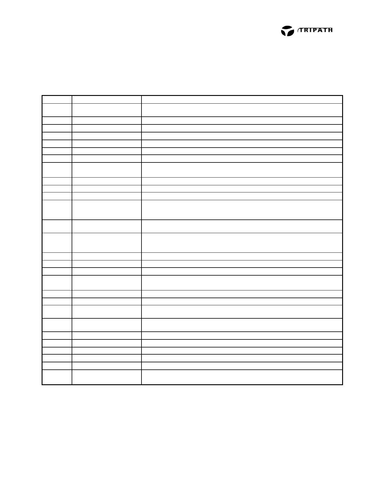
TECHNICAL INFORMATION
Pin Description
Pin
1
2,48
3,47
4,46
5,45
6, 7
8, 9
10, 40
12, 31
13, 16
14, 18
15
17
19
20, 25
21, 26
22, 23
24
27, 35
28,34
29
30
32
33, 37
39
41, 42
43, 44
11, 36,
38
Function
VN10
LO2, LO1
LO2COM, LO1COM
HO2COM, HO1COM
HO2, HO1
OCS2LN, OCS2LP
OCS2HP, OCS2HN
VBOOT2, VBOOT1
OCR2
FBKOUT1, FBKOUT2
FBKGND1, FBKGND2
HMUTE
DCOMP
BIASCAP
INV2, INV1
OAOUT2, OAOUT1
BBM0, BBM1
MUTE
V5
AGND
VPPSENSE
VNNSENSE
REF
OCR1
VNN
OCS1LN, OCS1LP
OCS1HP, OCS1HN
NC
Description
“Floating” supply input for the FET drive circuitry. This voltage must be stable
and referenced to VNN.
Low side gate drive output (Channel 2 & 1)
Kelvin connection to source of low-side transistor (Channel 2 & 1)
Kelvin connection to source of high-side transistor (Channel 2 & 1)
High side gate drive output (Channel 2 & 1)
Over Current Sense inputs, Channel 2 low-side
Over Current Sense inputs, Channel 2 high-side
Bootstrapped voltage to supply drive to gate of high-side FET
(Channel 2 & 1)
Over-current threshold adjustment (Channel 2)
Switching feedback (Channels 1 & 2)
Ground Kelvin feedback (Channels 1 & 2)
Logic Output. A logic high indicates both amplifiers are muted, due to the
mute pin state, or a “fault” such as an overcurrent, undervoltage, or
overvoltage condition.
Internal mode selection. This pin must be grounded for proper device
operation.
Bandgap reference times two (typically 2.5VDC). Used to set the common
mode voltage for the input op amps. This pin is not capable of driving external
circuitry.
Inverting inputs of Input Stage op amps. (Channels 2 & 1)
Outputs of Input Stage op amps. (Channels 2 & 1)
Break-before-make timing control to prevent shoot-through in the output FETs.
Logic input. A logic high puts the amplifier in mute mode. Ground pin if not
used. Please refer to the section, Mute Control, in the Application Information.
5V power supply input.
Analog ground.
Positive supply voltage sense input. This pin is used for both over and
under voltage sensing for the VPP supply.
Negative supply voltage sense input. This pin is used for both over and under
voltage sensing for the VNN supply.
Used to set internal bias currents. The pin voltage is typically 1.1V.
Over-current threshold adjustment (Channel 1)
Negative supply voltage.
Over Current Sense inputs, Channel 1 low-side
Over Current Sense inputs, Channel 1 high-side
Not connected (bonded) internally. To minimize coupling between pins, tie
these pins to AGND (pin34).
6
TA3020, Rev 2.1, 01.01
Share Link: