SMH4811 Ver la hoja de datos (PDF) - Summit Microelectronics
Número de pieza
componentes Descripción
Fabricante
SMH4811 Datasheet PDF : 16 Pages
| |||
SMH4811A
Figure 4
The 2.5Vref and 5Vref outputs are used to support the
peripheral circuits. In this example ENPG is pulled high to
the self-generated 5VREF.
The U1 circuitry is a temperature sensor that is effectively
a safety shut down circuit tied into the EN/TS input. If the
LMV331 drives its output low it will immediately turn off the
VGATE output.
The physical implementation of the board pins (see Note
2.) ensures the add-in card has power to the SMH4811,
but power to the backend circuits cannot be turned on until
the card is properly seated.
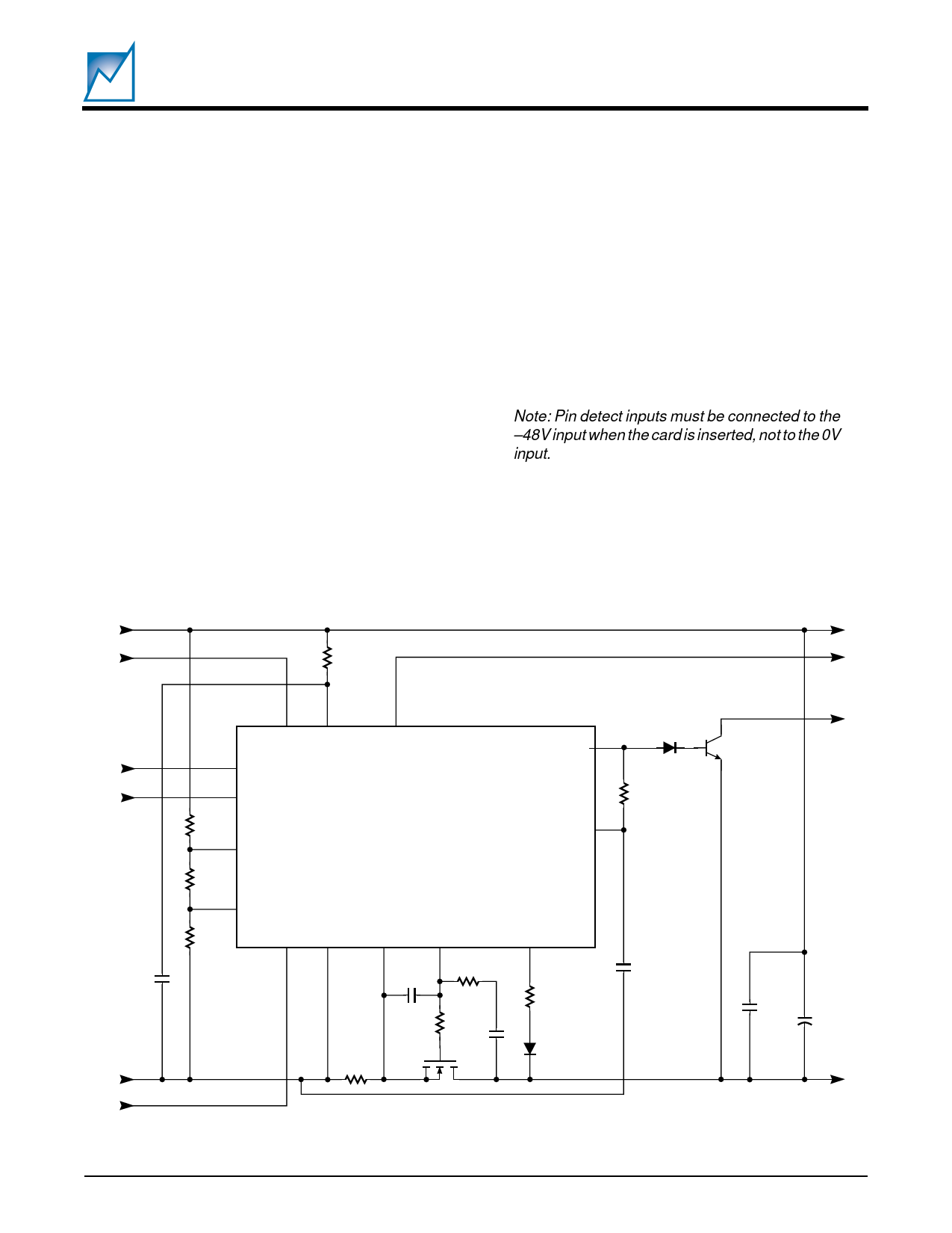
Figure 5
The polarity of the PG# output is reversed. EN/TS and
ENPG are under the control of the host system.
Figure 6
A circuit for controlling a DC/DC converter with a remote
off/on function. It should be noted the board layout for the
DC/DC converters is critical for proper operation. Most
manufacturers will have detailed technical notes to assist
with this. An excellent note is “Application Guidelines for
On-Board Power Converters” from Lucent Technologies.
Figure 7
A circuit for controlling a dual DC/DC converter with a
remote off/on function.
Note: Pin detect inputs must be connected to the
–48V input when the card is inserted, not to the 0V
input.
48V
RD
PD1# VDD
EN/TS
CBFAULT#
PG
1N4148
PG#
MM6T-
A06LT1
ENPG
EN/TS
47kΩ
R3
UV
SMH4811A
25.50VREF
R2
OV
R1
PD2# VSS CBSENSE VGATE
DRAIN
SENSE
100nF
25V
0V
1kΩ
100nF
20mΩ
10Ω RV*
10nF
100nF
1kΩ
1N4148
100nF
100V
4.7µF
100V
Figure 5. Generic Hot Swap implementation
SUMMIT MICROELECTRONICS, Inc.
2044 4.1 8/1/00
11
Share Link: 