S1A Ver la hoja de datos (PDF) - Electronics Industry
Número de pieza
componentes Descripción
Fabricante
S1A Datasheet PDF : 2 Pages
| |||
Certificate TH97/10561QM
Certificate TW00/17276EM
S1A ~ S1M
SURFACE MOUNT RECTIFIERS
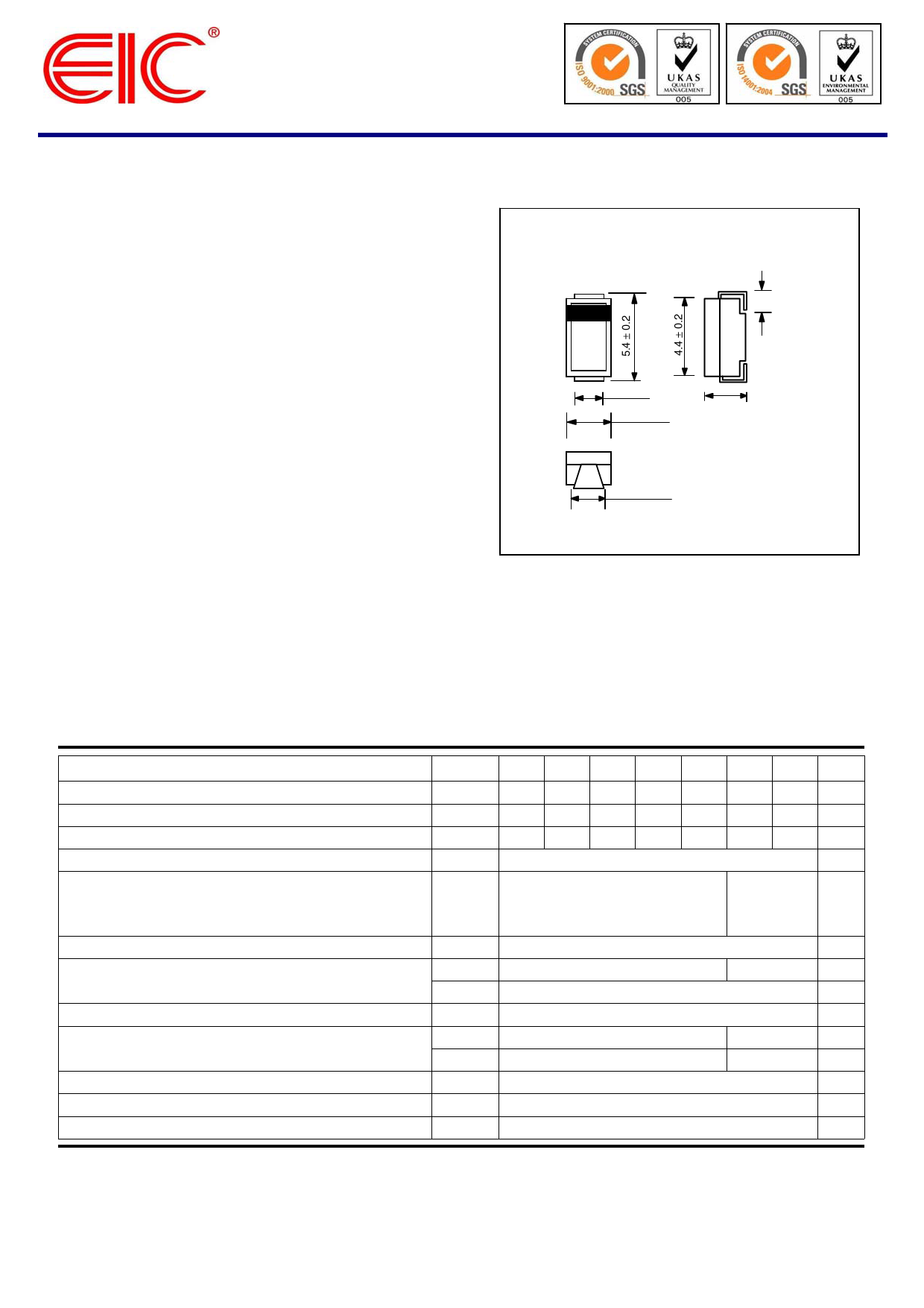
SMA
PRV : 50 - 1000 Volts
1.3 ± 0.2
Io : 1.0 Ampere
FEATURES :
* High current capability
* High surge current capability
* High reliability
* Low reverse current
* Low forward voltage drop
* Pb / RoHS Free
1.8 ± 0.2
2.7 ± 0.2
2.3 ± 0.2
1.8 ± 0.2
MECHANICAL DATA :
* Case : SMA Molded plastic
* Epoxy : UL94V-O rate flame retardant
* Polarity : Color band denotes cathode end
* Mounting position : Any
* Weight : 0.060 gram (Approximately)
Dimensions in millimeters
MAXIMUM RATINGS AND ELECTRICAL CHARACTERISTICS
Rating at 25 °C ambient temperature unless otherwise specified.
Single phase, half wave, 60 Hz, resistive or inductive load.
For capacitive load, derate current by 20%.
RATING
Maximum Repetitive Peak Reverse Voltage
Maximum RMS Voltage
Maximum DC Blocking Voltage
Maximum Average Forward Current (See fig. 1)
Peak Forward Surge Current
8.3ms Single half sine wave Superimposed
on rated load (JEDEC Method) TL = 110 °C
Maximum Instantaneous Forward Voltage at IF = 1.0 A.
Maximum DC Reverse Current
Ta = 25 °C
at rated DC Blocking Voltage
Ta = 125 °C
Typical Reverse Recovery Time (Note 1)
Typical thermal resistance (Note 2)
Typical Junction Capacitance at 4.0V, 1 MHz
Junction Temperature Range
Storage Temperature Range
SYMBOL S1A S1B S1D S1G S1J
VRRM 50 100 200 400 600
VRMS 35 70 140 280 420
VDC
50 100 200 400 600
IF
1.0
IFSM
40
VF
IR
IR(H)
Trr
RθJA
RθJL
CJ
TJ
TSTG
1.1
1.0
50
1.8
75
27
12
- 55 to + 150
- 55 to + 150
S1K S1M UNIT
800 1000 V
560 700 V
800 1000 V
A
30
A
V
5.0
μA
μA
μs
85
°C/W
30
°C/W
pF
°C
°C
Notes :
(1) Reverse Recovery Test Conditions : IF = 0.5 A, IR = 1.0 A, Irr = 0.25 A.
(2) Thermal resistance from junction to ambient and from junction to lead mounted on P.C.B. with 0.2 x 0.2” (5.0 x 5.0mm) copper pad areas
Page 1 of 2
Rev. 04 : October 26, 2006
Share Link: 