CMX589A Ver la hoja de datos (PDF) - CML Microsystems Plc
Número de pieza
componentes Descripción
Fabricante
CMX589A Datasheet PDF : 24 Pages
| |||
GMSK Modem
CMX589A
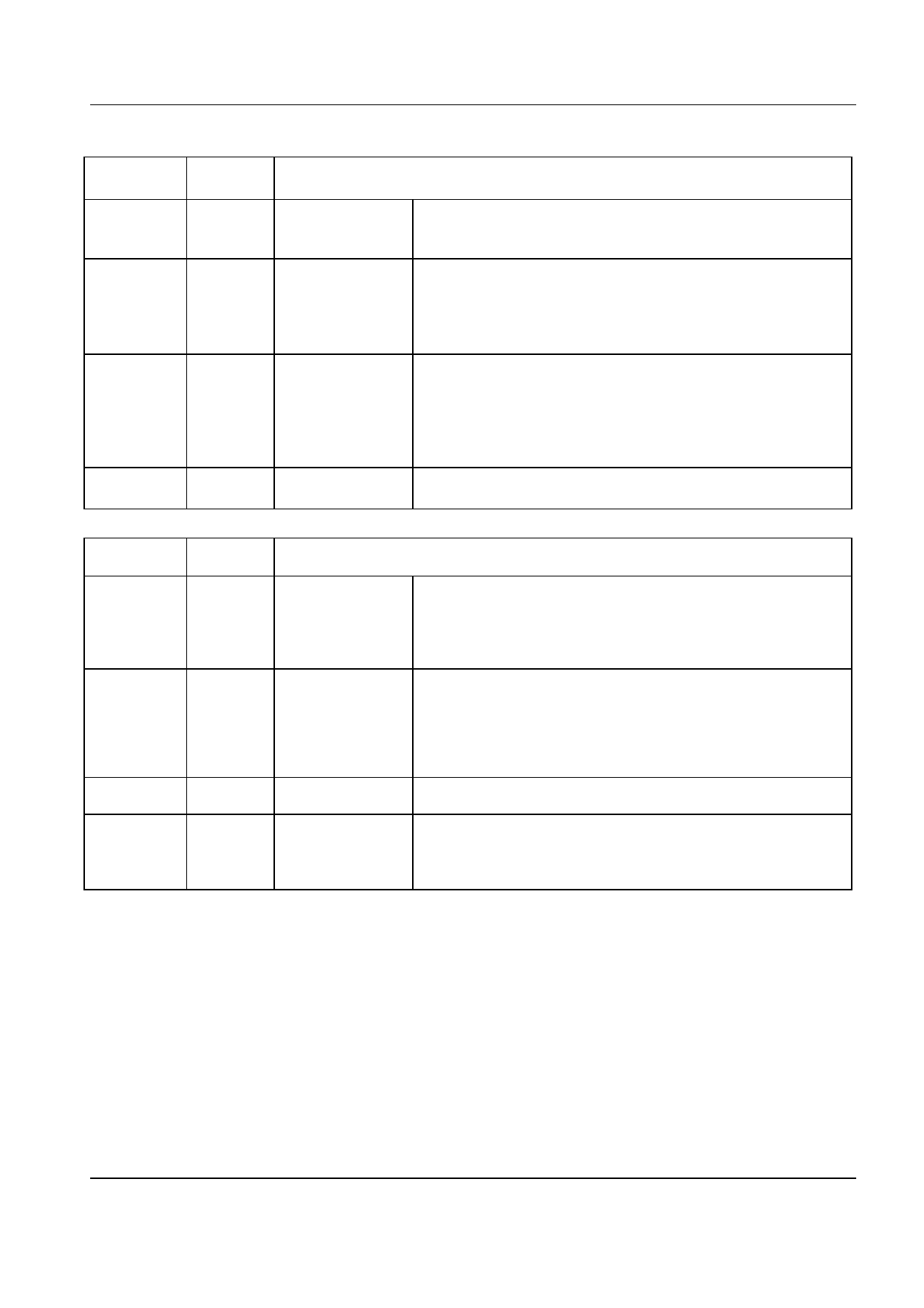
PLLacq
1
1 to 0
0
0
Rx
HOLDN
1
1
1
0
PLL Action
Acquire
Sets the PLL bandwidth wide enough to allow a lock to the
received signal in less than 8 zero crossings. This mode will
operate as long as PLLacq is a logic “1”.
Medium
Bandwidth
The correction applied to the extracted clock is limited to a
maximum of ±1/16th bit-period for every two received zero-
crossings. The PLL operates in this mode for a period of
about 30 bits immediately following a 1 to 0 transition of the
PLLacq input, provided that the Rx HOLDN input is a logic ‘1’.
Narrow
Bandwidth
The correction applied to the extracted clock is limited to a
maximum of ±1/64th bit-period for every two received zero-
crossings. The PLL operates in this mode whenever the Rx
HOLDN Input is a logic ‘1’ and PLLacq has been a logic ‘0’ for
at least 30 bit periods (after Medium Bandwidth operation for
instance).
Hold
The PLL feedback loop is broken, allowing the Rx Clock to
freewheel during signal fade periods.
Table 5: PLL Action Measurement Operational Modes
RxDCacq
0 to 1
Rx
HOLDN
X
1
X
0
1
0
0
X = Do not care
Rx Level Measure Action
Clamp
Fast Peak Detect
Averaging Peak
Detect
Hold
Operates for one bit-time after a 0 to 1 transition of the
RXDCacq input. The external capacitors are rapidly charged
towards a voltage mid-way between the received signal input
level and VBIAS, with the charge time-constant being of the
order of 0.5 bit-time.
The voltage detectors act as peak-detectors, one capacitor is
used to capture the positive-going signal peaks of the Rx
Filter output signal and the other capturing the negative-going
peaks. The detectors operate in this mode whenever the
RXDCacq input is at a logic ‘1’, except for the initial 1-bit
Clamp-mode time.
Provides a slower but more accurate measurement of the
signal peak amplitudes.
The capacitor charging circuits are disabled so that the
outputs of the voltage detectors remain substantially at the
last readings (discharging very slowly [time-constant approx.
2,000 bits] towards VBIAS).
Table 6: Rx Level Measurement Operational Modes
4.2.3 Rx Clock Extraction
Synchronized by a PLL circuit to zero-crossings of the incoming data, the Rx Clock Extraction circuitry controls
the Rx Clock output. The Rx Clock is also used internally by the Data Extraction circuitry. The PLL parameters
can be varied by the Rx Circuit Control inputs PLLacq and Rx HOLDN to operate in one of four PLL modes as
described in Table 5 and Table 6.
4.2.4 Rx Data Extraction
The Rx Data Extraction circuit decides whether each received bit is a 1 or 0 by sampling the received signal,
after filtering, and comparing the sample values to an adaptive threshold derived from the Level Measuring
circuit. This threshold is adapted from bit to bit to compensate for intersymbol interference caused by the and
limiting of the overall transmission path and the Gaussian premodulation filter. Extracted data is output from
the Rx Data pin, and should be sampled externally on the rising edge of the Rx CLK.
© 1998 Consumer Microcircuits Limited
10
D/589A/3
Share Link: 