PLUTO Ver la hoja de datos (PDF) - Zarlink Semiconductor Inc
Número de pieza
componentes Descripción
Fabricante
PLUTO Datasheet PDF : 15 Pages
| |||
PLUTO
PROGRAMMING and CONTROL
The control modes for Pluto can be set via external pins or via a 3 wire serial interface. On initialising Pluto control is from
external pins but can then be set for programming from the serial interface by setting the appropriate bit in a serial input word.
The Rx second LO synthesiser is programmed via the serial interface: the Tx IF synthesiser is fixed and requires no programming.
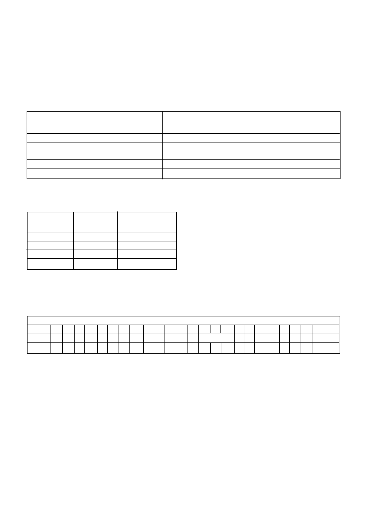
Mode Control - External
The control modes are set by the pins SLEEPB, FMB and IDLEB as shown in the table below:
SLEEPB
(Pin 9)
0
1
1
1
1
FMB
(Pin 7)
X
0
0
1
1
IDLEB
(Pin 5)
X
0
1
0
1
Mode
Sleep Mode
FM Receive only
FM Receive and Transmit
CDMA Receive only
CDMA Receive and Transmit
Aux ADC Selection - External
The auxiliary analog to digital converters can be selected via pins S0 and S1 as shown in the table below:
S1
(Pin 39)
0
0
1
1
S0
(Pin 33)
0
0
0
1
ADC
selected
ADC<0>
ADC<1>
ADC<2>
ADC<3>
ADC selection can also be programmed to be via serial interface if required
Serial Interface
The 3 wire serial interface (SDATA, SCLK and SLATCH) is programmed using 24 bit words as shown below. Timing
details are shown in Figure 8.
MSB
LSB
23 22 21 20 19 18 17 16 15 14 13 12 11 10 9 8 7 6 5 4 3 2 1 0
WORD1 0 0 0 0 0 X X RXC
RXDIV<13:0>
00
WORD2 SOP FMB IDB SLB 0 0 0 0 0 0 AD1 AD0 TST 0 0 0 0 0 MXS CTB 0 0 0 1
X
RXC
RXDIV<13:0>
SOP
SLB, IDB, FMB
TST
AD1, AD0
MXS
CTB
unused
RX Synth comparison frequency :0 = 30kHz, 1 = 5kHZ
RX Synth divider ratio
External/ Serial mode selection: 0 = Ext, 1 = Serial
Sleep, Idle and FM mode control bits (serial mode)
Test Mode Control - This is for test purposes only and should be set to 0
Aux ADC select bits (serial mode)
External / Serial Aux ADC select: 0 = Ext
Enable Rx Calibration: 0 = calibration mode
If SOP is high mode control is via serial bits FMB, IDB and SLB, instead of external pins FMB, IDLEB and SLEEPB.
If MXS is high then ADC selection is via AD1, AD0 instead of S<1>, S<0>
8
Share Link: 