P142-155.52 Ver la hoja de datos (PDF) - Connor-Winfield Corporation
Número de pieza
componentes Descripción
Fabricante
P142-155.52 Datasheet PDF : 2 Pages
| |||
2111 Comprehensive Drive
Aurora, Illinois 60505
Phone: 630-851-4722
Fax: 630-851-5040
www.conwin.com
Notes
Notes
1) Includes initial tolerance, deviation over temperature, supply and load variations, shock, vibration and 20 years
aging.
2) When the oscillator is disabled, the outputs are at High Impedance. Output is enabled with no connection on pad 1.
3) Output must be terminated into 50 ohms to Vcc – 2V or Thevenin equivalent.
4) Duty Cycle measured at 50% of output swing.
Ordering Information
P
1
2
3 - 155.52M
Type:
LVPECL
Clock Series
5x7mm
Temperature Range:
1 = 0 to 70° C
2 = -40 to 85° C
3 = 0 to 85° C
4 = -20 to 70° C
Frequency Stability:
4 = +/-20 ppm
1 = +/-25 ppm
2 = +/-50 ppm
3 = +/-100 ppm
Supply Voltage:
2 = 2.5Vdc.
3 = 3.3Vdc.
Output Frequency:
Frequency Format
-xxx.xM Min.*
-xxx.xxxxxxM Max.*
*Amount of numbers
after the decimal point.
M = MHz
Example: P123-155.52M = LVPECL Clock, 0 to 70°C, +/-50ppm, 3.3Vdc @ 155.52 MHZ
Package Characteristics
Table 5.0
Package
Hermetically sealed ceramic package and metal cover.
Soldering Process
RoHS compliant, see solder profile on page 2.
Environmental Characteristics
Table 6.0
Vibration:
Vibration per Mil Std 883E Method 2007.3 Test Condition A
Shock:
Mechanical Shock per Mil Std 883E Method 2002.4 Test Condition B.
Soldering:
SMD product suitable for Convection Reflow soldering. Peak
temperature 260 C. Maximum time above 220 C, 60 seconds.
Solderability
Solderability per Mil Std 883E Method 2003
Pad Connections - Enable / Disable Function
Table 7.0
Pad Connection
1 Enable / Disable
2
N/C
3
Ground
4
Q Output
5
Q Output
Enable / Disable
Function (Pad 1)
High or Open
Low
6
Vcc
Model Matrix
Frequency
Tolerance
±20ppm
P142
P442
P342
P242
P143
P443
P343
P243
Frequency
Tolerance
±25ppm
P112
P412
P312
P212
P113
P413
P313
P213
Frequency
Tolerance
±50ppm
P122
P422
P322
P222
P123
P423
P323
P223
Frequency
Tolerance
±100ppm
P132
P432
P332
P232
P133
P433
P333
P233
Tape and Reel Specifications
Table 8.0
Output
Enable
Disable (High Impedance)
Supply
Voltage
2.5Vdc
2.5Vdc
2.5Vdc
2.5Vdc
3.3Vdc
3.3Vdc
3.3Vdc
3.3Vdc
Table 9.0
Temperature
Range
0 to 70°C
-20 to 70°C
0 to 85°C
-40 to 85°C
0 to 70°C
-20 to 70°C
0 to 85°C
-40 to 85°C
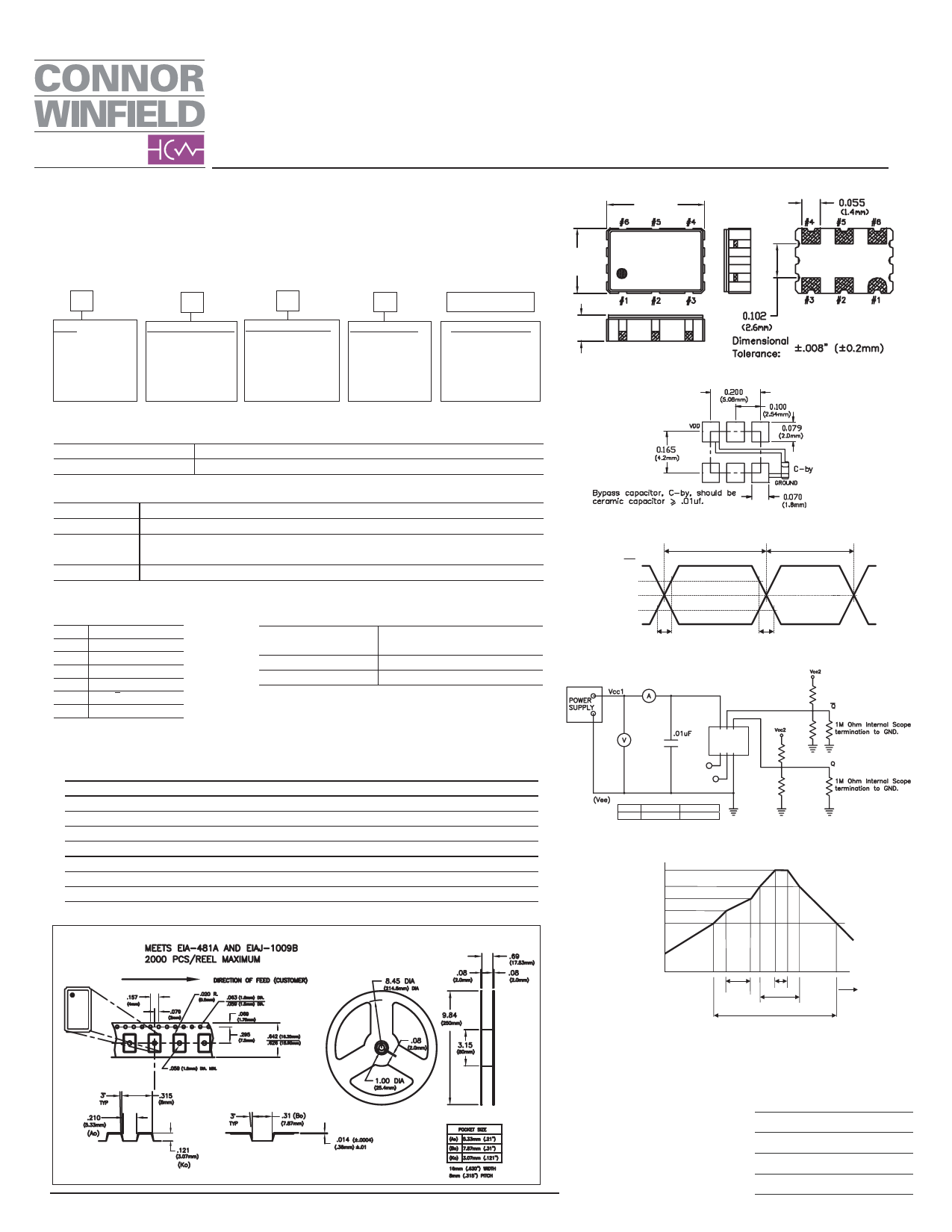
Package Outline
0.275
(7.0mm)
0.197
(5.0mm)
CW 0745
P123
155.52M
0.059
(1.5mm)
Suggested Pad Layout
LVPECL Output Waveform
Duty Cycle
Q
80%
50%
20%
Q
tr
Test Circuit
65 4
1 23
E/D
N/C
Vcc
2.5V
3.3V
R1 / R3
250 Ohms
130 Ohms
R2 /R4
62.5Ohms
82 Ohms
Solder Profile
Temperature
260°C
220°C
180°C
150°C
120°C
tf
R3
R4
R1
R2
260°C
1
Specifications subject to change without notice. All dimensions in inches. © Copyright 2008 The Connor-Winfield Corporation
0
120 S
Max.
10 S
60 S
Max.
Time
360 Sec. Max.
US Headquarters:
630-851-4722
European Headquarters:
+353-61-472221
Bulletin
Page
Revision
Date
Ec217
2 of 2
06
18 Apr 2008
Share Link: 