MT91600 Ver la hoja de datos (PDF) - Zarlink Semiconductor Inc
Número de pieza
componentes Descripción
Fabricante
MT91600 Datasheet PDF : 18 Pages
| |||
MT91600
Data Sheet
Application
The following Application section is intended to demonstrate to the user the methods used in calculating and
selecting the external programming components in implementing the MT91600 as an analog line interface in a
communication system. The programming component values calculated below results in the optimum performance
of the device.
Refer to Figure 5 for MT91600 components designation.
Component Selection
Feed Resistors (R1, R2)
The selection of feed resistors, R1 and R2, can significantly affect the performance of the MT91600. It is
recommended that their values fall in the range of:
200Ω <= R1 <= 250Ω
where, R1 = R2
The resistors should have a tolerance of 1% (0.15% matched) and a power rating of 1 Watt.
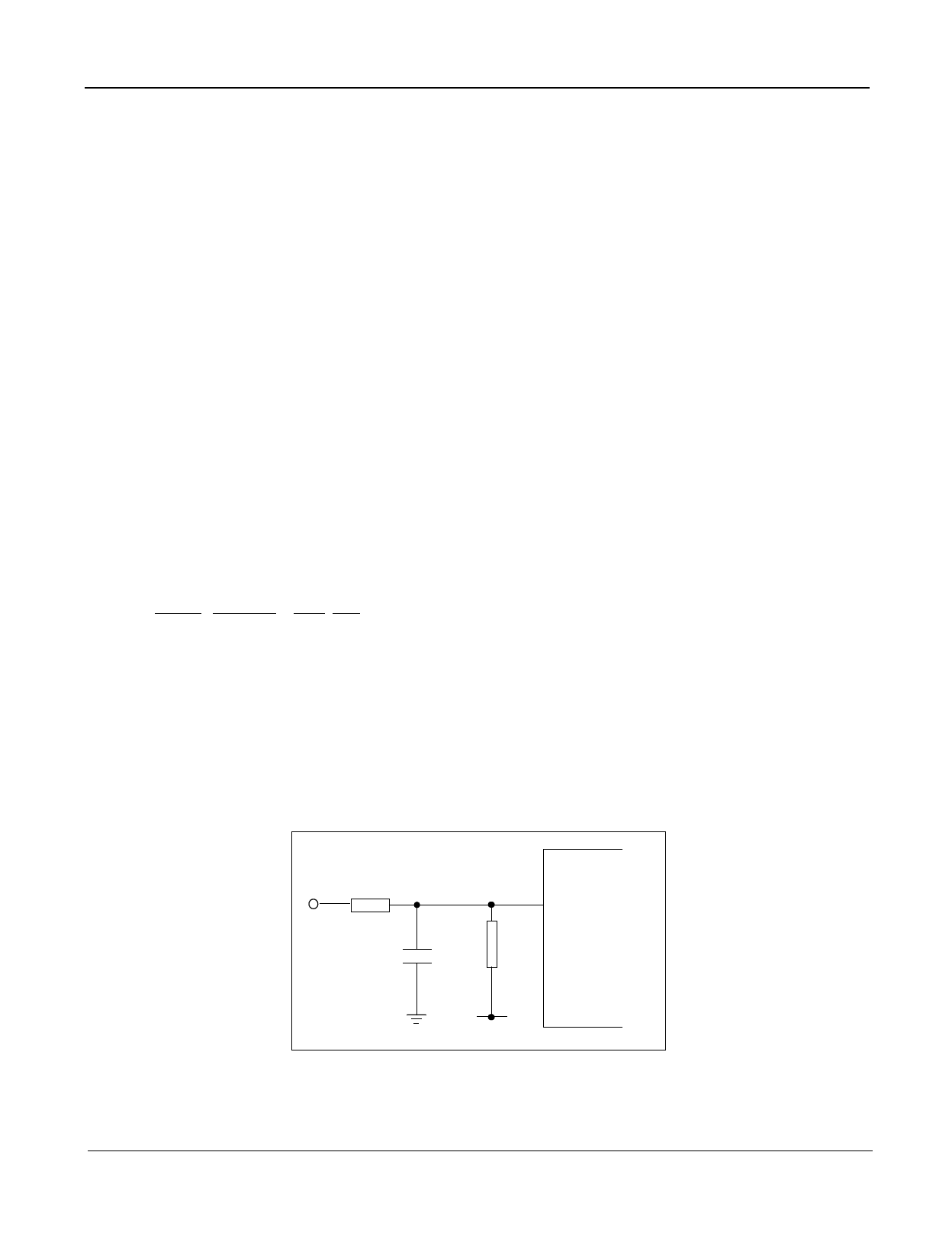
Loop Current Setting (R3, R4, C9)
By using a resistive divider network, (Figure 3), it is possible to maintain the required voltage at Vref to set ILOOP.
The loop current programming is based on the following relationship:
ILOOP = - [ F * VLC + G * VBAT] * Ko * H
(R1 +R2)
where,
F = R4 / (R4 + R3)
G = R3 / (R4 +R3)
Ko = 200000 / (200000 + (R4//R3) )
H = 1.07
ILOOP is in Ampere
From Figure 3 with R1 = R2 = 220Ω
For ILOOP = 25mA, VLC = 0V, Vbat=-48V
R3
43kΩ
VLC
6 VREF
C9
100nF
R4
130kΩ MT91600
VBAT
Figure 3 - Resistor Divider
6
Zarlink Semiconductor Inc.
Share Link: 