ML4425CP Ver la hoja de datos (PDF) - Fairchild Semiconductor
Número de pieza
componentes Descripción
Fabricante
ML4425CP Datasheet PDF : 16 Pages
| |||
ML4425
PRODUCT SPECIFICATION
Back EMF Sensing PLL Commutation Control
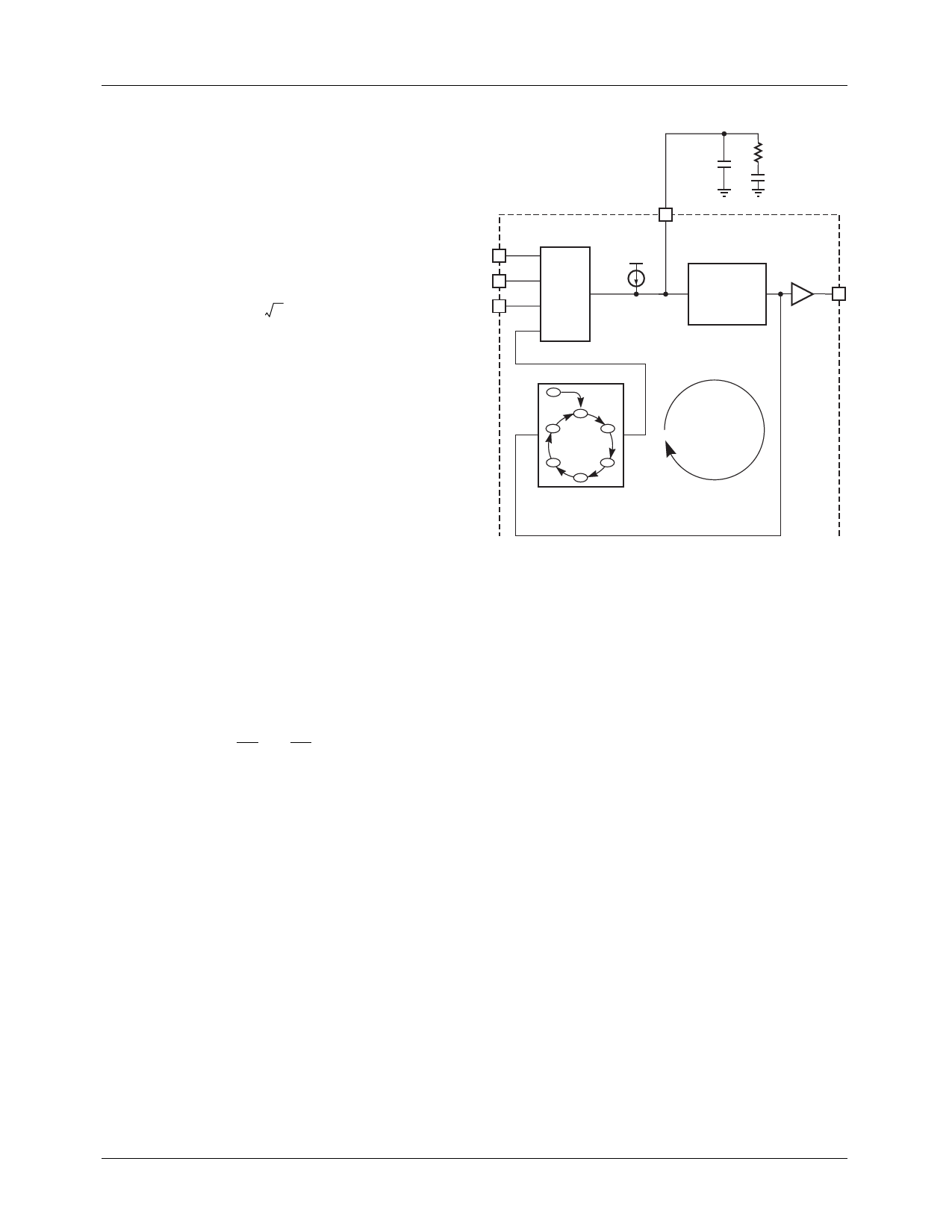
Three blocks form a phase locked loop that locks the com-
mutation clock onto the back EMF signal: the commutation
state machine, the voltage controlled oscillator, and the back
EMF sampler. The complete phase locked loop is illustrated
in Figure 7. The phased locked loop requires a lead lag filter
that is set by external components on SPEED FB. The com-
ponents are selected as follows:
CSPEEDFB1
=
0.25
×
-K----O----1-
M
×
---I--n-------1-------d0------0-----N-----S2---2×-----f--V---C----O---2--
(6a)
RSPEEDFB = 2 × M × In1----0d---0-- × N-----S-----×----K-----Of--V--1--C--×-O----(--1-----–----M------) (6b
CSPEEDFB2 = CSPEEDFB1 × (M – 1)
(6c)
Start-Up Sequence
When power is first applied to the ML4425 and the motor is
at rest, the back EMF is equal to zero. The motor needs to be
rotating for the back EMF sampler to lock onto the rotor
position and commutate the motor. The ML4425 uses an
open loop start-up technique to bring the rotor from rest up
to a speed fast enough to allow back EMF sensing. Start-up
is comprised of three modes: align mode, ramp mode, and
run mode.
Align Mode (RESET)
Before the motor can be started, the rotor must be in a known
position. When power is first applied to the ML4425, the
controller is reset into the align mode. Align mode turns on
the output drivers LB, HA, and HC which aligns the motor
into a position 30 electrical degrees before the center of the
first commutation state. This is shown as state R in the com-
mutation states of Table 1. Align mode must last long enough
to allow the motor and its load to settle into this position. The
align mode time is set by a capacitor connected to the CAT
pin as shown in Figure 8. CAT is charged by a constant
750µA current from GND to 1.5 V until the align comparator
trips to end the align mode. A starting point for CAT is calcu-
lated as follows:
CAT = t--S-----×-----7---.--5-----×1----.1--5--0-V--–---7----×-----a----m-----p--
(7)
If the align time is not long enough to allow the rotor to settle
for reliable starting, then increase CAT until the desired per-
formance is achieved.
CSPEEDFB1
RSPEEDFB
CSPEEDFB2
FB A
22
FB B
23
FB C
24
20
SPEED
FB
VDD
BACK 500nA
EMF
SAMPLER
VOLTAGE
CONTROLLED
OSCILLATOR
VCO/TACH
13
R
A
F
B
E
C
D
COMMUTATION
STATE MACHINE
PHASE
LOCKED
LOOP
Figure 7. Back EMF Commutation Phase Locked Loop
Ramp Mode
At the end of align mode the controller goes into ramp mode.
Ramp mode starts commutating through the states A through
F as shown in Table 1. This ramps up the commutation fre-
quency, and therefore the motor speed, for a fixed length of
time. This allows the motor to reach a sufficient speed for the
back EMF sampler to lock commutation onto the motor’s
back EMF. The amount of time the ML4425 stays in ramp
mode is determined by a capacitor connected to the CRT pin
as shown in Figure 8. CRT is charged by a constant 750µA
current from GND to 1.5 V until the ramp comparator trips
to end the ramp mode. This gives a fixed ramp time. CRT is
calculated as follows:
CRT = 2----π-----×-----J--I--M×-----A5---X--×---×--1--K-0----–t--7×----×-3----a-×---m--N---p-----×-----K----V--
(8)
The rate at which the ML4425 ramps up the motor speed is
determined by a fixed 500µA current source on the SPEED
FB pin. The current sources charges up the PLL filter com-
ponents causing the VCO frequency to ramp up. During
ramp mode, the back EMF sampler is disabled to allow con-
trol of the ramping to be set only by the 500µA current
source. The ramp based on the SPEED FB filter is generally
too fast for the motor to keep up, so a capacitor from CRR to
SPEED FB can be added to slow down the ramping rate. The
optimal ramp rate is based on the motor and load parameters
and is can be adjusted by varying the value of CRR.
10
REV. 1.0.2 7/2/01
Share Link: 