MF604F Ver la hoja de datos (PDF) - Unspecified
Número de pieza
componentes Descripción
Fabricante
MF604F Datasheet PDF : 12 Pages
| |||
Product Specification
MF604F
4.5. Test method :
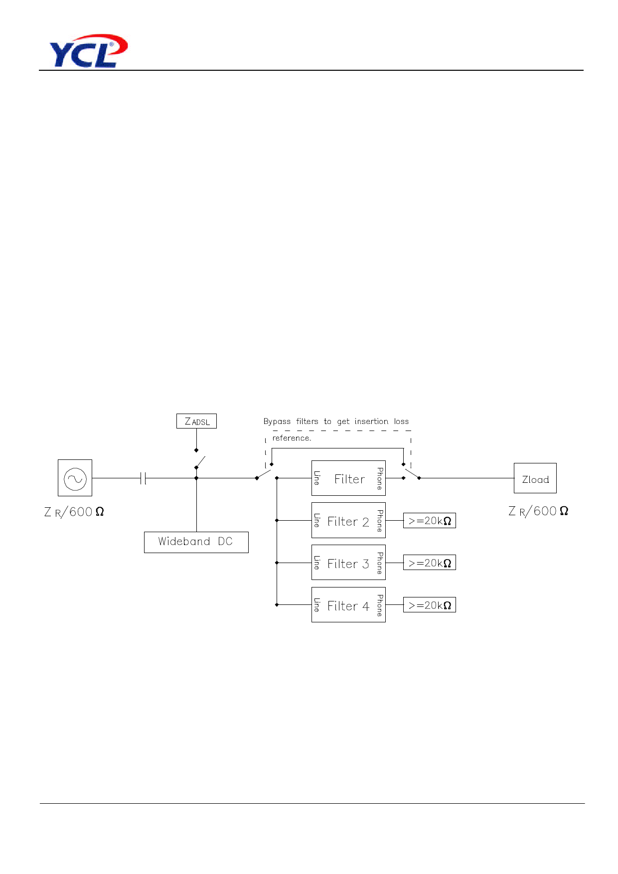
4.5.1. Insertion loss test setup :
The insertion loss of a device connected into a given transmission system is defined as the
ratio, expressed in dB, of the load power available(before and after insertion ) delivered to
the output network beyond the point of insertion at a given frequency. In general , the
insertion loss of a device inserted in a given transmission system is mainly caused by
internal component resistive loss while all of the impedance between source , load and
device interface having been matched. To perform the insertion loss measurement ,thru
calibration must be done prior the testing . General Insertion loss equation can be
expressed as following. Insertion loss = 20 log V2 / V1 dB where
V1 = the measured voltage value of load without LPF in circuit.
V2 = the measured voltage value of load with LPF in circuit.
The test setup is shown in drawing below :
Note : ZR = 270 ohm + ( 750 ohm // 150nf )
Data sheet subject to change without notice
RDPS-MF050(R0)08/27/2002
SHEET 8 OF 12
Share Link: 