ICM7231 Ver la hoja de datos (PDF) - Intersil
Número de pieza
componentes Descripción
Fabricante
ICM7231 Datasheet PDF : 16 Pages
| |||
ICM7231, ICM7232
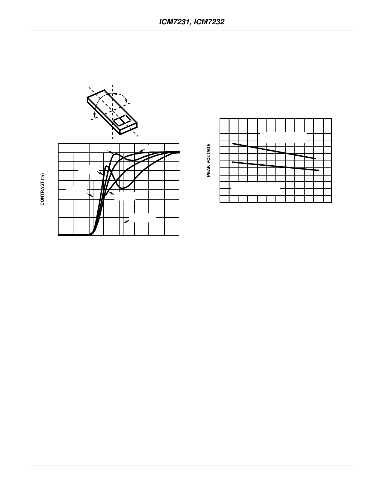
Figure 8 shows the curve of contrast versus applied RMS volt-
age for a liquid crystal material
typical value for 1/3 multiplexed
tailored for
displays in
VPEAK = 3.1V, a
calculators. Note
that the RMS OFF voltage VPEAK/3 ≈ 1V is just below the
“threshold” voltage where contrast begins to increase. This
places the RMS ON voltage at 2.1V, which provides about
85% contrast when viewed straight on.
0+
0-
specifying displays the following must be kept in mind: liquid
crystal material, polarizer, and seal materials.
A more important effect of temperature is the variation of
threshold voltage. For typical liquid crystal materials suitable for
multiplexing, the peak voltage has a temperature coefficient of -7
to -14mV/oC. This means that as temperature rises, the thresh-
old voltage goes down. Assuming a fixed value for VP, when the
threshold voltage drops below VPEAK/3 OFF segments begin to
be visible. Figure 9 shows the temperature dependence of peak
voltage for the same liquid crystal material of Figure 8.
6
100
TA = 25oC
90
θ = -10o
θ=0
80
70
θ = -30o
60
50
VOFF =
40
1.1VRMS
θ = +10o
30
20
VON = 2.1V
10
0
0
1
2
3
4
APPLIED VOLTAGE (VRMS)
FIGURE 8. CONTRAST vs APPLIED RMS VOLTAGE
All members of the ICM7231 and ICM7232 family use an internal
resistor string of three equal value resistors to generate the volt-
ages used to drive the display. One end of the string is connected
on the chip to VDD and the other end (user input) is available at
pin 2 (VDISP) on each chip. This allows the display voltage input
(VDISP) to be optimized for the particular liquid crystal material
used. Remember that VPEAK = VDD - VDISP and should be
three times the threshold voltage of the liquid crystal material
used. Also it is very important that pin 2 never be driven below
VSS. This can cause device latchup and destruction of the chip.
Temperature Effects and Temperature Compensation
The performance of the LCD material is affected by tempera-
ture in two ways. The response time of the display to changes
of applied RMS voltage gets longer as the display tempera-
ture drops. At very low temperatures (-20oC) some displays
may take several seconds to change a new character after the
new information appears at the outputs. However, for most
applications above 0oC this will not be a problem with avail-
able multiplexed LCD materials, and for low-temperature
applications, high-speed liquid crystal materials are available.
At high temperature, the effect to consider deals with plastic
materials used to make the polarizer.
Some polarizers become soft at high temperatures and per-
manently lose their polarizing ability, thereby seriously
degrading display contrast. Some displays also use sealing
materials unsuitable for high temperature use. Thus, when
5
PEAK VOLTAGE FOR
90% CONTRAST (ON)
4
3
2
1
PEAK VOLTAGE FOR
10% CONTRAST (OFF)
0
-10
0
10
20
30
40
50
AMBIENT TEMPERATURE (oC)
FIGURE 9. TEMPERATURE DEPENDENCE OF LC THRESHOLD
For applications where the display temperature does not
vary widely, VPEAK may be set at a fixed voltage chosen to
make the RMS OFF voltage, VPEAK/3, just below the thresh-
old voltage at the highest temperature expected. This will
prevent OFF segments turning ON at high temperature (this
at the cost of reduced contrast for ON segments at low
temperatures).
For applications where the display temperature may vary to
wider extremes, the display voltage VDISP (and thus VPEAK)
may require temperature compensation to maintain sufficient
contrast without OFF segments becoming visible.
Display Voltage and Temperature Compensation
These circuits allow control of the display peak voltage by
bringing the bottom of the voltage divider resistor string out at
pin 2. The simplest means for generating a display voltage
suitable to a particular display is to connect a potentiometer
from pin 2 to VSS as shown in Figure 10. A potentiometer with
a maximum value of 200kΩ should give sufficient range of
adjustment to suit most displays. This method for generating
display voltage should be used only in applications where the
temperature of the chip and display won’t vary more than
±5oC (±9oF), as the resistors on the chip have a positive tem-
perature coefficient, which will tend to increase the display
peak voltage with an increase in temperature. The display
voltage also depends on the power supply voltage, leading to
tighter tolerances for wider temperature ranges.
9-28
Share Link: 