LT1949 Ver la hoja de datos (PDF) - Linear Technology
Número de pieza
componentes Descripción
Fabricante
LT1949 Datasheet PDF : 8 Pages
| |||
LT1949
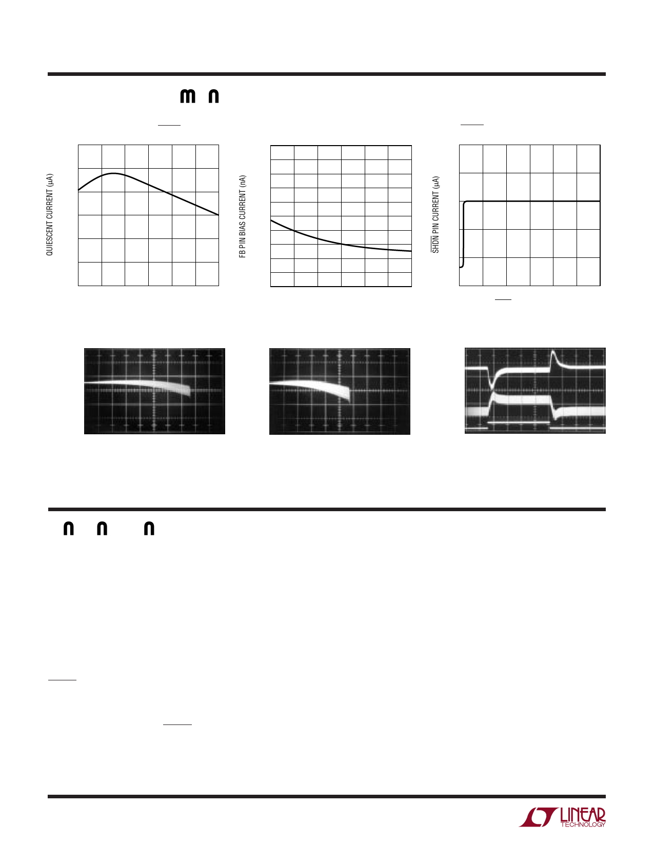
TYPICAL PERFOR A CE CHARACTERISTICS
Quiescent Current, SHDN = 0V
26
25
24
23
22
21
20
–50 –25 0
25 50
TEMPERATURE (°C)
75 100
1317 TPC10
Load Regulation
FB Pin Bias Current
40
36
32
28
24
20
16
12
8
4
0
–50 –25 0
25 50
TEMPERATURE (°C)
Load Regulation
75 100
1317 TPC11
SHDN Pin Current
2
1
0
–1
–2
–3
0
1
2
3
4
5
6
SHDN PIN VOLTAGE (V)
1317 TPC12
Transient Response
VOUT
50mV/DIV
DC
COUPLED
OFFSET
ADDED
ILOAD 25mA/DIV
VIN = 3V
VOUT = 10V
L1 = 10µH, SUMIDA CD54
COUT = 10µF CERAMIC
VOUT
50mV/DIV
DC
COUPLED
OFFSET
ADDED
1949 G10
ILOAD 50mA/DIV
VIN = 4V
VOUT = 10V
L1 = 10µH, SUMIDA CD54
COUT = 10µF CERAMIC
VOUT
100mV/DIV
AC COUPLED
1949 G11
IL
500mA/DIV
ILOAD
200mA
100mA
50µs/DIV
VIN = 3.3V
VOUT = 10V
CIRCUIT OF FIGURE 1
1949 G12
PI FU CTIO S
VC (Pin 1): Compensation Pin for Error Amplifier. Con-
nect a series RC network from this pin to ground. Typical
values for compensation are a 68k/330pF combination
when using ceramic output capacitors. Minimize trace
area at VC.
FB (Pin 2): Feedback Pin. Reference voltage is 1.24V.
Connect resistor divider tap here. Minimize trace area at
FB. Set VOUT according to: VOUT = 1.24V(1 + R1/R2).
SHDN (Pin 3): Shutdown. Pull this pin low for shutdown
mode (only the low-battery detector remains active).
Leave this pin floating or tie to a voltage between 1.4V and
6V to enable the device. SHDN pin is logic level and need
only meet the logic specification (1.4V for high, 0.4V for
low).
GND (Pin 4): Ground. Connect directly to local ground
plane.
SW (Pin 5): Switch Pin. Connect inductor/diode here.
Minimize trace area at this pin to keep EMI down.
VIN (Pin 6): Supply Pin. Must be bypassed close to the
pin.
LBI (Pin 7): Low-Battery Detector Input. 200mV refer-
ence. Voltage on LBI must stay between ground and
700mV. Low-battery detector remains active in shutdown
mode.
LBO (Pin 8): Low-Battery Detector Output. Open collec-
tor, can sink 10µA. A 1MΩ pull-up is recommended.
4
Share Link: 