IP2002 Ver la hoja de datos (PDF) - International Rectifier
Número de pieza
componentes Descripción
Fabricante
IP2002 Datasheet PDF : 12 Pages
| |||
iP2002
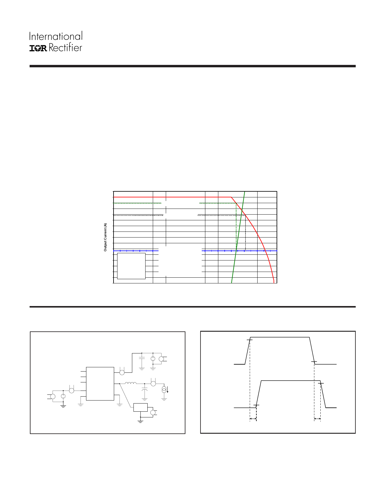
Example 2) Adjusting for SOA Temperature:
(Fig. 3)
(Fig. 4)
(Fig. 5)
(Fig. 6)
Normalized SOA Temperature for input voltage ≈ -0.6°C
Normalized SOA Temperature for output voltage ≈ 8.4°C
Normalized SOA Temperature for frequency ≈ -1.8°C
Normalized SOA Temperature for inductor value ≈ 1.1°C
TX axis intercept temp adjustment = - 0.6°C + 8.4°C - 1.8°C + 1.1°C ≈ 7.1°C
Assuming TCASE = 100°C & TPCB = 90°C:
The following example shows how the SOA current is adjusted for a TX increase of 7.1°C.
Case Temperature (ºC)
0
32
10
20
30
40
50
60
70
80
30
28
Unadjusted SOA Current
26
24
Adjusted SOA Current
22
20
18
16
14
12
10
VIN = 12V
8
6
4
VOUT = 1.3V
fSW = 1MHz
2 L = 0.30uH
Safe
Operating
Area
0
0
10
20
30
40
50
60
70
80
PCB Temperature (ºC)
90
100
110
120
TX
90
100
110
120
PIN = VIN Average x IIN Average
PDD = VDD Average x IDD Average
POUT = VOUT Average x IOUT Average
PLOSS = (PIN + PDD) - POUT
Average
Input
Current
Average
VDD
Current
PRDY
ENABLE
PWM
VIN
A
VSW
A
Average
VDD
V DC
Voltage
VDD
SGND
PGND
iPP20021
Average
DC
V
Input
Voltage
Average Output
Current
A
Averaging
Average
Circuit
V
AOvOuetrpauugtteput
VVolotaglteage
(VOUT)
Fig 8. Power Loss Test Circuit
www.irf.com
90%
PWM
10%
90%
VSW
10%
td(on)
td(off)
Fig 9. Timing Diagram
7
Share Link: 