QL6325-E Ver la hoja de datos (PDF) - QuickLogic Corporation
Número de pieza
componentes Descripción
Fabricante
QL6325-E Datasheet PDF : 56 Pages
| |||
QL6325E Eclipse-E Data Sheet Rev. F
QuickWorks Design Software
The QuickWorks package provides the most complete ESP and FPGA software solution from design entry
to logic synthesis, to place and route, to power calculation, and simulation. The package provides a solution
for designers who use third-party tools from Cadence, Mentor, OrCAD, Synopsys, Viewlogic, and other third-
party tools for design entry, synthesis, or simulation.
Programmable Logic Architectural Overview
The Eclipse-E logic cell structure is presented in Figure 2. This architectural feature addresses today's register-
intensive designs.
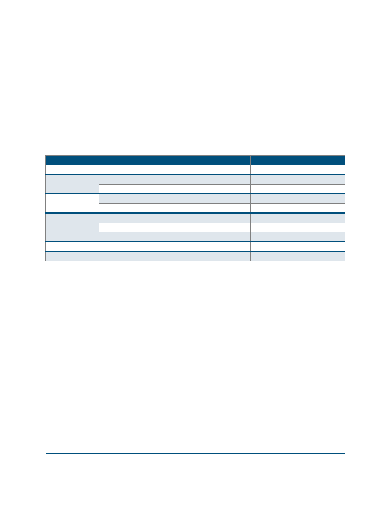
Table 1: Performance Standards
Function
Multiplexer
Parity Tree
Counter
FIFO
Clock-to-Out
System clock
Description
16:1
24
36
16 bit
32 bit
128 x 32
128 x 64
256 x 16
Slowest Speed Grade
2.8 ns
3.4 ns
4.6 ns
275 MHz
250 MHz
197 MHz
188 MHz
208 MHz
4 ns
200 MHz
Fastest Speed Grade
2.4 ns
2.9 ns
3.9 ns
328 MHz
300 MHz
235 MHz
266 MHz
248 MHz
3.3 ns
300 MHz
The Eclipse-E logic cell structure presented in Figure 2 is a dual register, multiplexor-based logic cell. It is
designed for wide fan-in and multiple, simultaneous output functions. Both registers share CLK, SET, and
RESET inputs. The second register has a two-to-one multiplexer controlling its input. The register can be
loaded from the NZ output or directly from a dedicated input.
NOTE: The input PP is not an “input” in the classical sense. It is a static input to the logic cell and selects
which path (NZ or PS) is used as an input to the Q2Z register. All other inputs are dynamic and can
be connected to multiple routing channels.
The complete logic cell consists of two six-input AND gates, four two-input AND gates, seven two-to-one
multiplexers, and two D flip-flops with asynchronous SET and RESET controls. The cell has a fan-in of 30
(including register control lines), fits a wide range of functions with up to 17 simultaneous inputs, and has six
outputs (four combinatorial and two registered). The high logic capacity and fan-in of the logic cell
accommodates many user functions with a single level of logic delay while other architectures require two or
more levels of delay.
2
•
•••
••
www.quicklogic.com
© 2005 QuickLogic Corporation
Share Link: 