ELM413P Ver la hoja de datos (PDF) - Elm Electronics
Número de pieza
componentes Descripción
Fabricante
ELM413P Datasheet PDF : 4 Pages
| |||
ELM413
Absolute Maximum Ratings
Storage Temperature....................... -65°C to +150°C
Ambient Temperature with
Power Applied....................................-40°C to +85°C
Voltage on VDD with respect to VSS............ 0 to +7.5V
Voltage on any other pin with
respect to VSS........................... -0.6V to (VDD + 0.6V)
Note:
Stresses beyond those listed here will likely damage
the device. These values are given as a design
guideline only. The ability to operate to these levels
is neither inferred nor recommended.
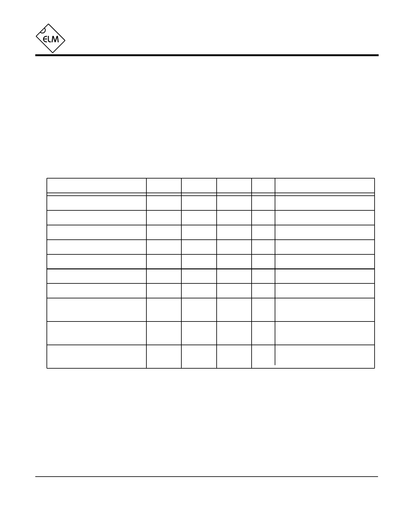
Electrical Characteristics
All values are for operation at 25°C and a 5V supply, unless otherwise noted. For further information, refer to note 1 below.
Characteristic
Minimum Typical Maximum Units
Conditions
Supply voltage, VDD
3.0
5.0
5.5
V
VDD rate of rise
0.05
V/ms see note 2
Average supply current, IDD
1.0
2.4
mA VDD = 5V, see note 3
Maximum allowable input current
-0.5
+0.5
mA trigger input only, see note 4
Input low voltage
VSS
0.75
V W0 or W1
Input high voltage
4.25
VDD
V W0 or W1
Trigger pulse width
4
µsec during idle periods, see note 5
Trigger input thresholds
2.8
4.25
V transition point - rising edge
0.75
1.3
V transition point - falling edge
Output high voltage
4.4
V Current (source) = 8 mA
4.0
V Current (source) = 13 mA
Output low voltage
0.4
V Current (sink) = 8 mA
0.75
V Current (sink) = 13 mA
Notes:
1. This integrated circuit is produced with a Microchip Technology Inc.’s PIC12C5XX as the core embedded
microcontroller. For further device specifications, and possibly clarification of those given, please refer to the
appropriate Microchip documentation.
2. This spec must be met in order to ensure that a correct power on reset occurs. It is quite easily achieved
using most common types of supplies, but may be violated if one uses a slowly varying supply voltage, as
may be obtained through direct connection to solar cells, or some charge pump circuits.
3. Device only. Does not include any current supplied to external components.
4. This is the maximum allowable current through the protection diodes when applying large voltages to the
trigger input (pin 5) through a current limiting resistance. With VDD > Vin > VSS, the circuit presents a typical
CMOS input load.
5. The trigger input is ignored during the warmup period.
ELM413DSA
Elm Electronics – Circuits for the Hobbyist
< http://www.elmelectronics.com/ >
3 of 4
Share Link: 