CS51221 Ver la hoja de datos (PDF) - ON Semiconductor
Número de pieza
componentes Descripción
Fabricante
CS51221 Datasheet PDF : 14 Pages
| |||
CS51221
APPLICATION INFORMATION
THEORY OF OPERATION
VOUT
Feed Forward Voltage Mode Control
In conventional voltage mode control, the ramp signal has
fixed rising and falling slope. The feedback signal is derived
solely from the output voltage. Consequently, voltage mode
control has inferior line regulation and audio susceptibility.
Feed forward voltage mode control derives the ramp
signal from the input line, as shown in Figure 3. Therefore,
the ramp of the slope varies with the input voltage. At the
start of each switch cycle, the capacitor connected to the FF
pin is charged through a resistor connected to the input
voltage. Meanwhile, the Gate output is turned on to drive an
external power switching device. When the FF pin voltage
reaches the error amplifier output VCOMP, the PWM
comparator turns off the Gate, which in turn opens the
external switch. Simultaneously, the FF capacitor is quickly
discharged to 0.3 V.
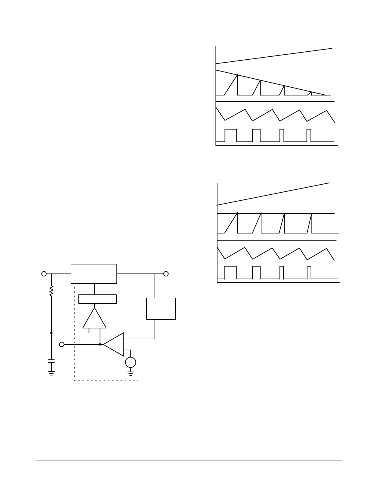
Overall, the dynamics of the duty cycle are controlled by
both input and output voltages. As illustrated in Figure 4,
with a fixed input voltage the output voltage is regulated
solely by the error amplifier. For example, an elevated
output voltage reduces VCOMP which in turn causes duty
cycle to decrease. However, if the input voltage varies, the
slope of the ramp signal will react immediately which
provides a much improved line transient response. As an
example shown in Figure 5, when the input voltage goes up,
the rising edge of the ramp signal increases which reduces
duty cycle to counteract the change.
VCOMP
FF
VIN
RTCT
GATE
Figure 4. Pulse Width Modulated by Output
Current with Constant Input Voltage
VIN
VCOMP
FF
IOUT
RTCT
VIN
Power Stage
VOUT
GATE
R
FF
COMP
C
GATE
Latch & Driver
PWM
−
+
Error Amplifier
+
−
Feedback
Network
FB
Figure 3. Feed Forward Voltage Mode Control
The feed forward feature can also be employed to provide
a volt−second clamp, which limits the maximum product of
input voltage and turn on time. This clamp is used in circuits,
such as Forward and Flyback converter, to prevent the
transformer from saturating. Calculations used in the design
of the volt−second clamp are presented in the Design
Guidelines section.
Figure 5. Pulse Width Modulated by Input Voltage
with Constant Output Current
Powering the IC & UVL
The Undervoltage Lockout (UVL) comparator has two
voltage references; the start and stop thresholds. During
power−up, the UVL comparator disables VREF (which
in−turn disables the entire IC) until the controller reaches its
VCC start threshold. During power−down, the UVL
comparator allows the controller to operate until the VCC
stop threshold is reached. The CS51221 requires only 50 mA
during startup. The output stage is held at a low impedance
state in lock out mode.
During power up and fault conditions, the Soft−Start
clamps the Comp pin voltage and limits the duty cycle. The
power up transition tends to generate temporary duty cycles
much greater than the steady state value due to the low
output voltage. Consequently, excessive current stresses
often take place in the system. Soft−Start technique
alleviates this problem by gradually releasing the clamp on
the duty cycle to eliminate the in−rush current. The duration
http://onsemi.com
8
Share Link: 