BTS650PE3180A Ver la hoja de datos (PDF) - Siemens AG
Número de pieza
componentes Descripción
Fabricante
BTS650PE3180A Datasheet PDF : 16 Pages
| |||
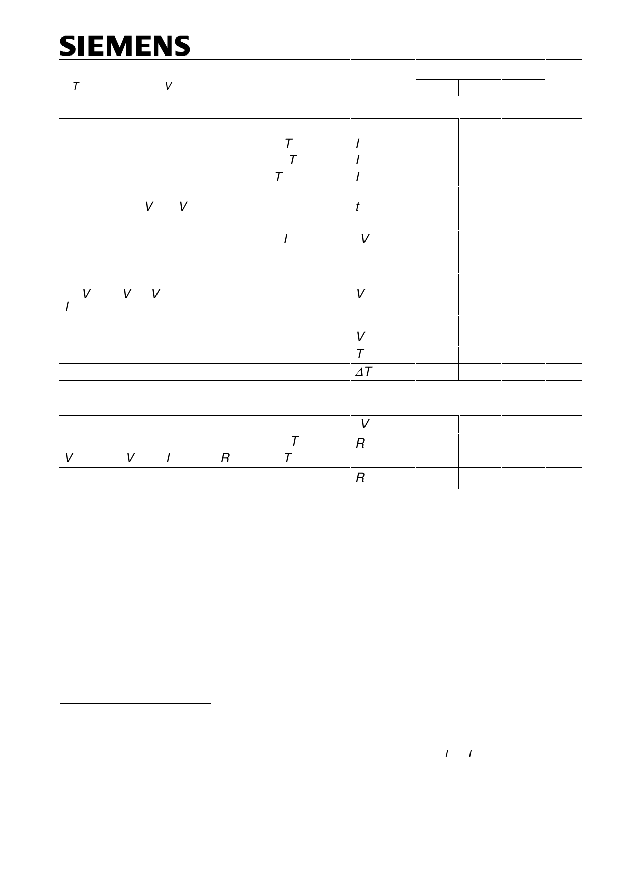
Parameter and Conditions
at Tj = -40 ... +150 °C, Vbb = 12 V unless otherwise specified
Symbol
Protection Functions
Short circuit current limit (Tab to pins 1,2,6,7)
VON = 12 V, time until shutdown max. 350 µs Tc =-40°C:
Tc =25°C:
Tc =+150°C:
Short circuit shutdown delay after input current
positive slope, VON > VON(SC)
min. value valid only if input "off-signal" time exceeds 30 µs
Output clamp 16)
(inductive load switch off)
IL= 40 mA:
see diagram Ind. and overvolt. output clamp page 8
Output clamp (inductive load switch off)
at VOUT = Vbb - VON(CL) (e.g. overvoltage)
IL= 40 mA
Short circuit shutdown detection voltage
(pin 4 to pins 1,2,6,7)
Thermal overload trip temperature
Thermal hysteresis
IL(SC)
IL(SC)
IL(SC)
td(SC)
-VOUT(CL)
VON(CL)
VON(SC)
Tjt
∆Tjt
Reverse Battery
Reverse battery voltage 17)
On-state resistance (Pins 1,2,6,7 to pin 4) Tj = 25 °C:
Vbb = -12V, VIN= 0, IL = - 20 A, RIS = 1 kΩ Tj = 150 °C:
Integrated resistor in Vbb line
-Vbb
RON(rev)
Rbb
BTS650P
Values
Unit
min typ max
-- 110 --
A
-- 130 180
65 115 --
80
-- 350 µs
14 16.5 20 V
39 42 47 V
--
6
150
--
-- 10
-- V
-- °C
-- K
--
-- 32 V
-- 5.4 7.0 mΩ
8.9 12.3
-- 120
-- Ω
)16 This output clamp can be "switched off" by using an additional diode at the IS-Pin (see page 8). If the diode
is used, VOUT is clamped to Vbb- VON(CL) at inductive load switch off.
)17 The reverse load current through the intrinsic drain-source diode has to be limited by the connected load
(as it is done with all polarity symmetric loads). Note that under off-conditions (IIN = IIS = 0) the power
transistor is not activated. This results in raised power dissipation due to the higher voltage drop across the
intrinsic drain-source diode. The temperature protection is not active during reverse current operation!
Increasing reverse battery voltage capability is simply possible as described on page 9.
Semiconductor Group
Page 5
1998-Nov.-2
Share Link: 