M64403FP Ver la hoja de datos (PDF) - MITSUBISHI ELECTRIC
Número de pieza
componentes Descripción
Fabricante
M64403FP Datasheet PDF : 17 Pages
| |||
PRELIMINARY NSootmicee:pTahrisamisentroict alimfinitaslasrpeescuifbicjaetciot nto. change.
MITSUBISHI ICs (LSI)
M64403FP
ERROR CORRECTION WITH VARIABLE LENGTH AND DISTANCE
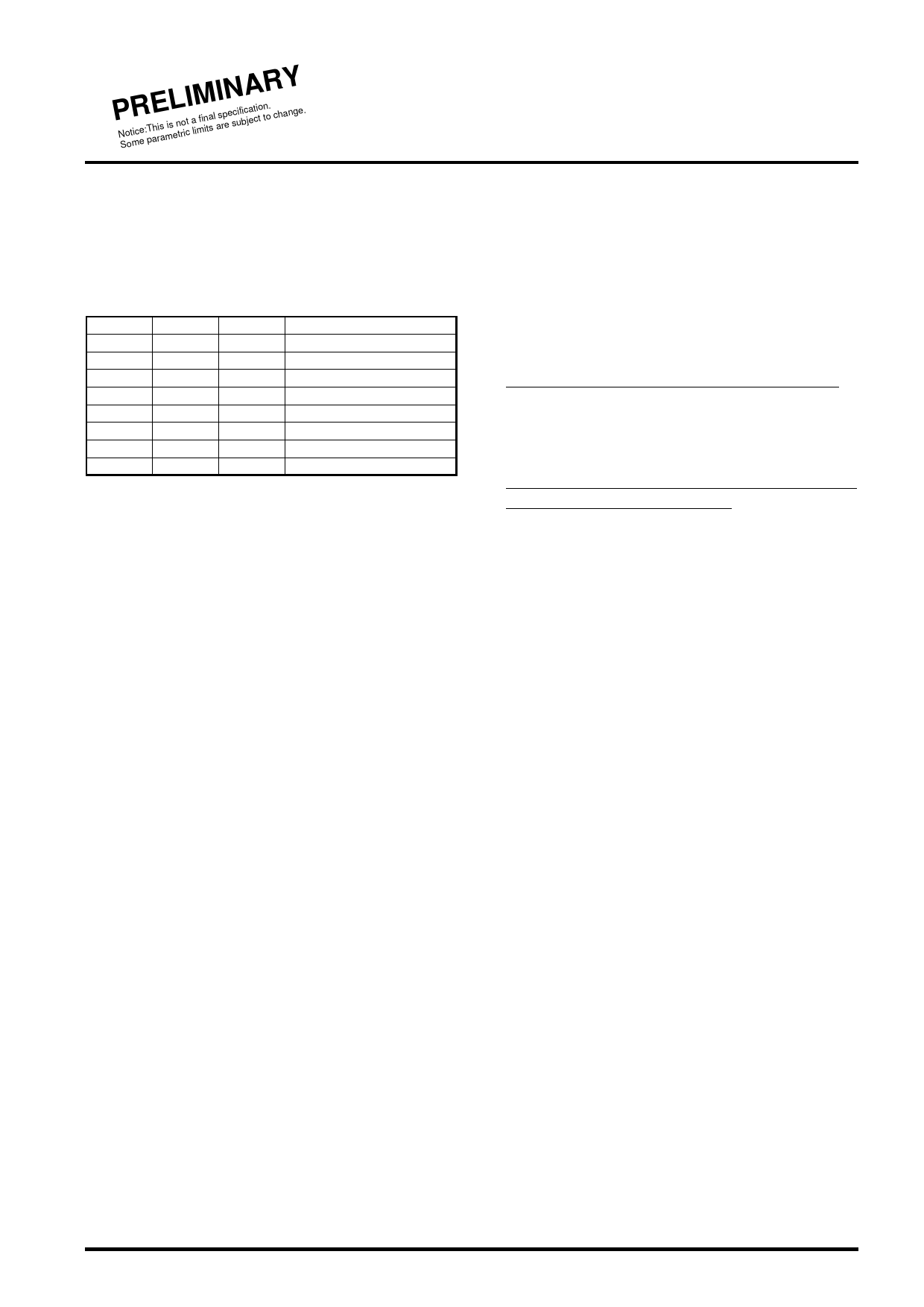
DECODE MODE SETTING METHOD
Decode mode is able to set at IRDY=H. Decode mode table is as
follows. Decode mode should be changed after all operations that
are set before changing.
Decode mode table
MOD0
0
1
0
1
0
1
0
1
MOD1
0
0
1
1
0
0
1
1
MOD2
0
0
0
0
1
1
1
1
mode
code (0) error correction
code (1) error correction
code (2) error correction
code (3) error correction
code (0) erasure correction
code (1) erasure correction
code (2) erasure correction
code (3) erasure correction
CODE WORD INPUT METHOD
Code word is able to input at IRDY=H. IRDY changes H to L when
head symbol for code word is input. And IRDY changes L to H
when the last symbol of code word is input.
DHEF should be H and DIEN should be L when the head symbol
of code word is input. DIEN is input enable signal for code word
and while it's L, input data is recognized as valid data and latched
to the internal circuit at rising edge of CLKI.
If the syndrome calculation for the 2nd code word finishes while the
1st code word is executed at Euclidean calculation stage, the
syndrome data that is latched internally is overwritten (called
syndrome collision) and the correcting operation for the 1st code
word is impossible. In this case, SYCR changes to H and informs
external of its status. (If the last symbol of code word is input at
SBFB=H, decoding is operated safely.)
SYCR which changes to H is reset by system reset (REST=L).
ERASURE FLAG INPUT METHOD AND
ERASURE CORRECTION MODE
Erasure correcting mode is set by the setting of erasure threshold
to address 8 to B for parameter register and the setting of
MOD2=H for decode mode signal. Erasure flag (EREN) should
input H by synchronization with symbol data of code word.
Follows are about erasure threshold.
(1) Constrained error correction mode is derived when the bit0 (D0)
of the parameter register address-E is set to L.
If the input erasure count is over the erasure threshold value(∗3),
the operation is adopted ordinary error correction mode by
force.
(2) Erasure correction priority mode is derived when the bit0 (D0)
of the parameter register address-E is set to H.
If the error is detected at syndrome calculation and erasure
count is over the erasure threshold value(∗4,) M64403FP regards
its operation as uncorrectable and correcting operation doesn't
execute.
In any cases ((∗3),(∗4)), EROV (erasure over flag) changes to H.
Share Link: 