M64403FP Ver la hoja de datos (PDF) - MITSUBISHI ELECTRIC
Número de pieza
componentes Descripción
Fabricante
M64403FP Datasheet PDF : 17 Pages
| |||
PRELIMINARY NSootmicee:pTahrisamisentroict alimfinitaslasrpeescuifbicjaetciot nto. change.
MITSUBISHI ICs (LSI)
M64403FP
ERROR CORRECTION WITH VARIABLE LENGTH AND DISTANCE
MICRO COMPUTER INTERFACE
Parameter register setting method (write) is described as follows.
(See page7 about sequence chart : See below diagram about
micro computer I/F and register table.)
1. Perform power on reset.
2. Set various parameters (code length-1, check byte length,
erasure correction threshold) to below parameter register table.
3. Set decode operation mode parameters to address-E. (See
address-E description)
See sequence chart page7 (micro computer I/F sequence) as for
read from parameter register, see below table as for register table.
Parameter register table
address (Hex) R/W
0
R/W
1
R/W
2
R/W
3
R/W
4
R/W
5
R/W
6
R/W
7
R/W
8
R/W
9
R/W
A
R/W
B
R/W
C
R
D
—
E
R/W
F
—
Initial (Hex)
00
00
00
00
00
00
00
00
00
00
00
00
—
—
—
—
set data (Hex)
≤FE
≤FE
≤FE
≤FE
≤10
≤10
≤10
≤10
≤10
≤10
≤10
≤10
—
—
—
—
description
code (0) code length-1
code (1) code length-1
code (2) code length-1
code (3) code length-1
code (0) check byte length
code (1) check byte length
code (2) check byte length
code (3) check byte length
code (0) erasure threshold
code (1) erasure threshold
code (2) erasure threshold
code (3) erasure threshold
real erasure counts which is derived from syndrome calculation
reserve
decode operation mode
reserve
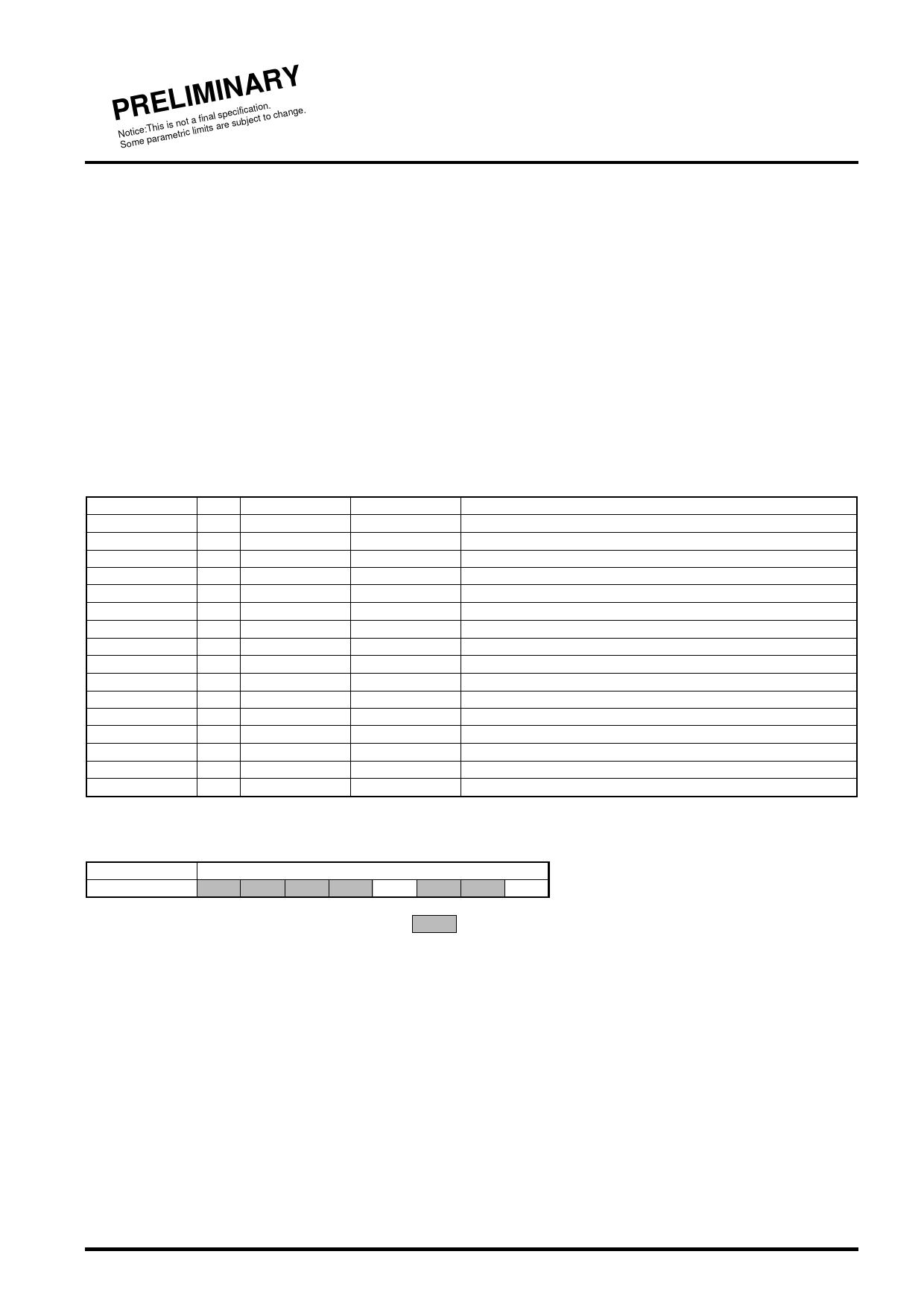
Address-E description
address (Hex)
data
E
D7 D6 D5 D4 D3 D2 D1 D0
means "0" fixed.
D0 (bit0) 0:constrained error correction mode
D3 (bit3) 0:error value output mode
1:erasure correction priority mode
1:internal correction mode
Share Link: 