74LCXH16245TTR Ver la hoja de datos (PDF) - STMicroelectronics
Número de pieza
componentes Descripción
Fabricante
74LCXH16245TTR
STMicroelectronics

74LCXH16245TTR Datasheet PDF : 10 Pages
| |||
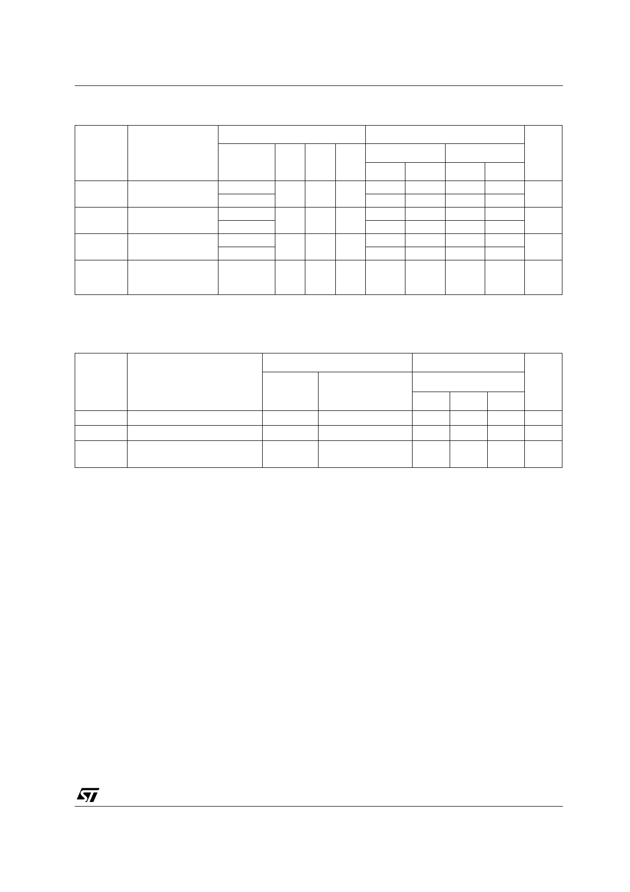
74LCXH16245
AC ELECTRICAL CHARACTERISTICS
Test Condition
Value
Symbol
Parameter
VCC
CL RL ts = tr -40 to 85 °C
-55 to 125 °C Unit
(V)
(pF) (Ω) (ns) Min. Max. Min. Max.
tPLH tPHL Propagation Delay
Time
2.7
3.0 to 3.6
50 500 2.5
1.5
1.5
5.2
4.5
1.5
1.5
6.0
5.3
ns
tPZL tPZH Output Enable Time
2.7
1.5
7.2
1.5
8.3
50 500 2.5
ns
3.0 to 3.6
1.5
6.5
1.5
7.3
tPLZ tPHZ Output Disable Time
2.7
1.5
6.9
1.5
7.5
50 500 2.5
ns
3.0 to 3.6
1.5
6.4
1.5
7.2
tOSLH Output To Output
3.0 to 3.6 50 500 2.5
1.0
tOSHL Skew Time (note1,
2)
1.0
ns
1) Skew is defined as the absolute value of the difference between the actual propagation delay for any two outputs of the same device switch-
ing in the same direction, either HIGH or LOW (tOSLH = | tPLHm - tPLHn|, tOSHL = | tPHLm - tPHLn|)
2) Parameter guaranteed by design
CAPACITIVE CHARACTERISTICS
Test Condition
Value
Symbol
Parameter
VCC
(V)
TA = 25 °C
Unit
Min. Typ. Max.
CIN
Input Capacitance
3.3
4
pF
COUT Output Capacitance
3.3
10
pF
CPD Power Dissipation Capacitance
3.3
(note 1)
fIN = 10MHz
VIN = 0 or VCC
50
pF
1) CPD is defined as the value of the IC’s internal equivalent capacitance which is calculated from the operating current consumption without
load. (Refer to Test Circuit). Average operating current can be obtained by the following equation. ICC(opr) = CPD x VCC x fIN + ICC/16 (per
circuit)
5/10
Share Link: