73K222AU Ver la hoja de datos (PDF) - TDK Corporation
Número de pieza
componentes Descripción
Fabricante
73K222AU Datasheet PDF : 40 Pages
| |||
73K222AU
Single-Chip Modem
with UART
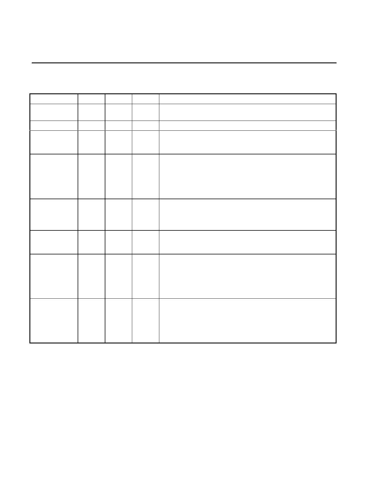
PIN DESCRIPTION
GENERAL
NAME
DIP
VDD
40
GND
20
VREF
19
ISET
9
XTL1
25
XTL2
24
CLK
21
RESET
10
STNDLN
15
PLCC
44
22
21
11
27
26
23
12
17
TYPE
I
I
O
I
I
I
O
I
I
DESCRIPTION
+5V Supply ±10%, bypass with a 0.1 and a 22 µF capacitor to
GND
System Ground
VREF is an internally generated reference voltage which is
externally bypassed by a 0.1 µF capacitor to the system
ground.
The analog current is set by connecting this pin to VDD through
a 2 MΩ resistor. ISET should be bypassed to GND.
Alternatively, an internal bias can be selected by connecting
ISET to GND, which will result in a larger worst-case supply
current due to the tolerance of on-chip resistors. Bypass with
0.1 µF capacitor if resistor is used.
These pins are connections for the internal crystal oscillator
requiring an 11.0592 MHz crystal. XTL2 can also be TTL driven
from an external clock. Connect a 10 MΩ resistor from XTL1 to
ground and a 1 MΩ resistor from XTL1 to XTL2
Output Clock. This pin is selectable under processor control to
be either the crystal frequency (which might be used as a
processor clock) or the output of the baud generator.
Reset. An active signal (high) on this pin will put the chip into an
inactive state. The control register bits (except the Receiver
Buffer, Transmitter Holding, and Divisor latches) will be reset.
The output of the CLK pin will be set to the crystal frequency.
An internal pull-down resistor permits power-on reset using a
0.1 µF capacitor connected to the 5V supply.
Single-port mode select (active high). In a single-port system
there is no local microprocessor and all the modem control is
done through the 16C450 parallel bus interface. The local
microprocessor interface is replaced with UART control signals
which allow the device to function as a digital UART as well as
modem.
4
Share Link: 