CA3165 Ver la hoja de datos (PDF) - Intersil
Número de pieza
componentes Descripción
Fabricante
CA3165 Datasheet PDF : 6 Pages
| |||
CA3165
+13V
R1
820
200
220
1W
1W
5%
±5%
6
5
CA3165E 4
TOP
7
VIEW
3
8
2
0.01µF
C6
C3
0.01µF
L1 SENSOR COIL,
INDUCTANCE ≈ 100µH,
UNLOADED Q ≈ 53
1
R6
220
6490 ± 0.15%
C2
L1
1500pF
SILVER
MICA
METALLIC TRIGGER WHEEL,
ONE TOOTH PER CYLINDER
VOUT
ALL RESISTORS 1/2 W ±5%
UNLESS OTHERWISE SPECIFIED
RESISTOR VALUES IN OHMS
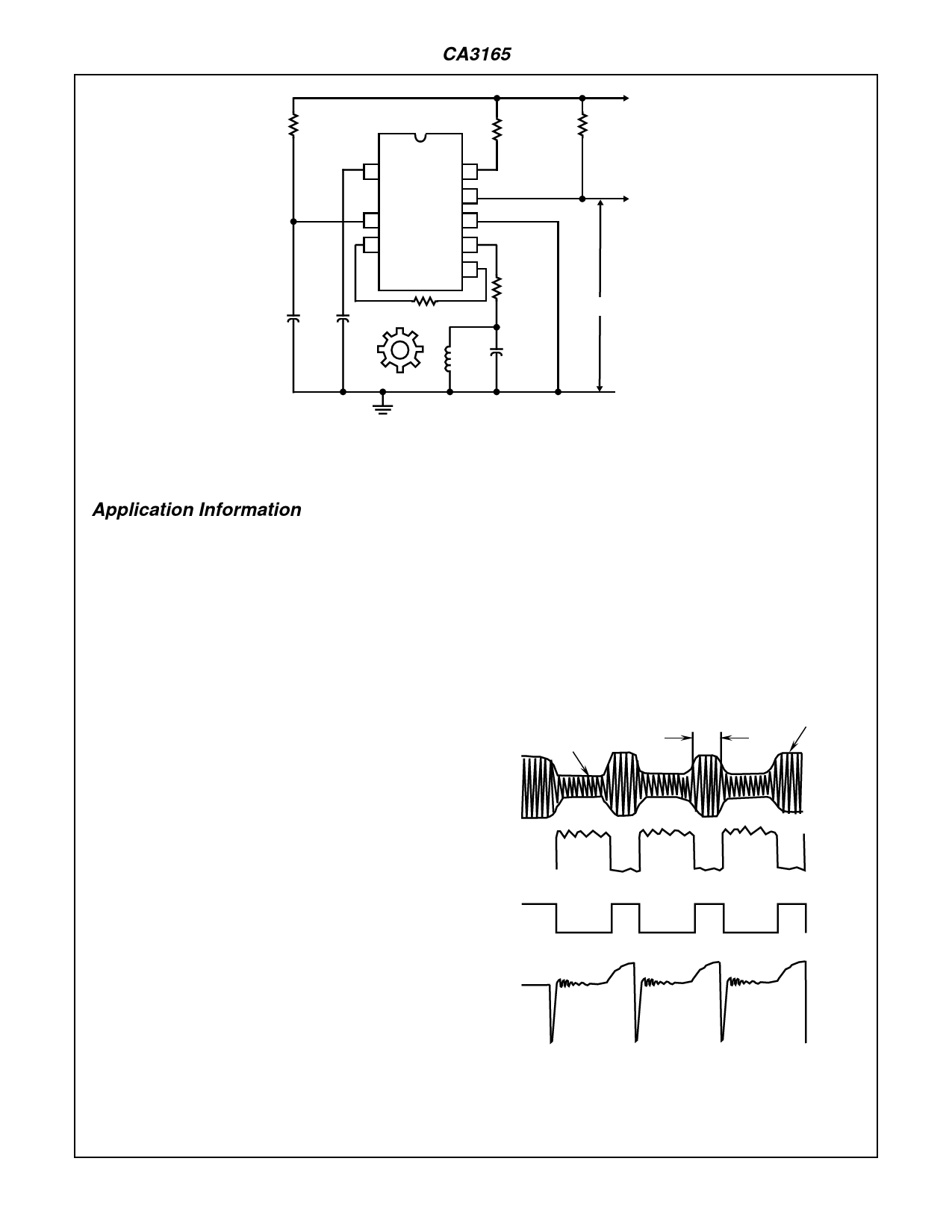
FIGURE 6. TYPICAL IGNITION SYSTEM USING THE CA3165E
Application Information
Figure 5 and Figure 6 show the application of the CA3165 in
a typical ignition system. The oscillator on the chip operates
at about 400kHz as determined by the tuned circuit L1, C2.
The amplitude of the oscillation is detected on the chip and
applied to a Schmitt trigger which sets the terminal voltage
as shown in the chart in Figure 1 and Figure 2 for the
unloaded condition of the oscillator. As a metallic tooth in the
rotor passes the coil L1, eddy-current losses occur which
reduce the Q of the resonant circuit and decrease the ampli-
tude of the oscillations to a level below that of a reference in
the detector circuit. The output terminals are then switched
to states as shown in the chart in Figure 1 and Figure 2 for
the loaded condition of the oscillator. The oscillation is main-
tained at this lower amplitude by switching in additional feed-
back in the oscillator circuit. The fact that the oscillator
continues to operate at some minimum level during this
dwell period eliminates timing variations which would occur if
the oscillator had to be restarted by random noise.
Spark occurs as terminal 4 is switched from high to low. The
output amplifier clamps terminal 4 low through the regulator
during the duration of the spark.
The Dwell period represents the time that terminal 10
(CA3165E1) or terminal 6 (CA3165E) is high, terminal 4 is
low, and the coil is charged.
The value of the oscillator feedback, resistor, RF, is selected
to set the dwell period. With a sintered-iron 8 f-tooth rotor, a
typical value of RF is 6500Ω for 28.5 degrees of dwell out of
a 45 degree cycle. For a star-type rotor and a particular coil
in a typical distributor, the feedback resistor would be larger
(typically 8800Ω) depending on clearances, coil geometry
and tooth shape.
For typical F-Tooth Rotor with Rod Sensor and 113µH of coil
inductance, the Q and frequency with respect to rotor posi-
tion was measured for the following positions
CENTER 46 at 377kHz
SLOT
6 at 390kHz
FIRE
15 at 381kHz
(Free air Q = 55.7 at 375kHz.)
OSCILLATOR
OSC
LOADED
DWELL
PERIOD
OSC
UN-
LOADED
HIGH
DETECTOR
TERM 10
LOW
HIGH
TERM 4
LOW
SPARK
DWELL
COIL
CHARGE
DWELL
FIGURE 7. TIMING SEQUENCE
10-30
Share Link: 