MAS110S06 Ver la hoja de datos (PDF) - Dynex Semiconductor
Número de pieza
componentes Descripción
Fabricante
MAS110S06 Datasheet PDF : 9 Pages
| |||
MAS110S
THERMAL AND MECHANICAL DATA
Symbol
Parameter
Rth(j-c)
Thermal resistance - junction to case
(Thyristor or diode)
R
th(c-h)
Thermal resistance - case to heatsink
(Thyristor or diode)
Tvj
Virtual junction temperature
Top
Operating temperature range
T
Storage temperature range
stg
Visol
Isolation voltage
-
Mounting torque
Conditions
dc
Mounting force 6Nm
with mounting compound.
-
-
Commoned terminals to base plate.
AC RMS, 1 min, 50Hz.
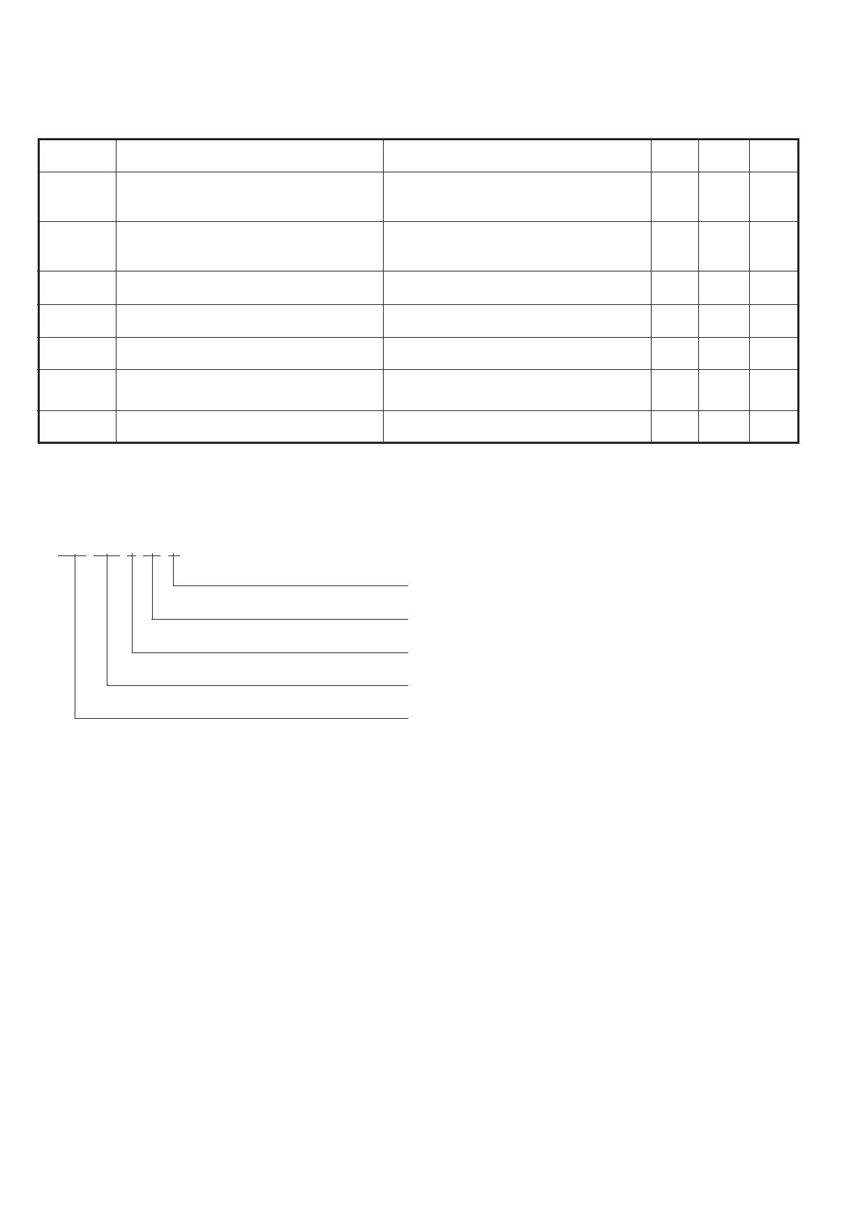
ORDERING INFORMATION
The module type number is made up as follows:
Examples:
MAS XXX S XX W
Turn-off time code
MAS 110 S 12 W
MAS 110 S 08 X
Voltage grade. VDRM/100
Single thyristor/diode configuration
Nominal IF(AV) at Tcase = 75˚C
Pressure contact asymmetric thyristor/diode module
Min. Max. Units
-
0.21 oC/W
-
0.07 oC/W
-
125
oC
-40
125
oC
-40 125
oC
-
2.5
kV
-
6.0 Nm
MODULE MOUNTING RECOMMENDATIONS
s Adequate heatsinking is required to maintain the base
temperature at 75oC if full rated current is to be achieved. Power
dissipation may be calculated by use of VT(TO) and rT information
and loss curves in accordance with standard formulae. We can
provide assistance with calculations or choice of heatsink if required.
s The heatsink surface must be smooth and flat; a surface finish
of N6 (32µin) and a flatness within 0.05mm (0.002") are
recommended.
s Immediately prior to mounting, the heatsink surface should be
lightly scrubbed with fine emery, Scotch Brite™ or a mild chemical
etchant and then cleaned with a solvent to remove oxide build up
and foreign material. Care should be taken to ensure no foreign
particles remain.
s An even coating of thermal compound (eg. Unial) should be
applied to both the heatsink and module mounting surfaces. This
should ideally be 0.05mm (0.002") per surface to ensure optimum
thermal performance.
s After application of thermal compound, place the module squarely
over the mounting holes, (or 'T' slots) in the heatsink. Using a
torque wrench, slowly tighten the recommended fixing bolts at
each end, rotating each in turn no more than 1/4 of a revolution at
a time. Continue until the required torque of 6Nm (55lb.ins) is
reached at both ends.
s It is not acceptable to fully tighten one fixing bolt before starting
to tighten the others. Such action may DAMAGE the module.
4/9
Share Link: 