16TTS08S Ver la hoja de datos (PDF) - International Rectifier
Número de pieza
componentes Descripción
Fabricante
16TTS08S Datasheet PDF : 8 Pages
| |||
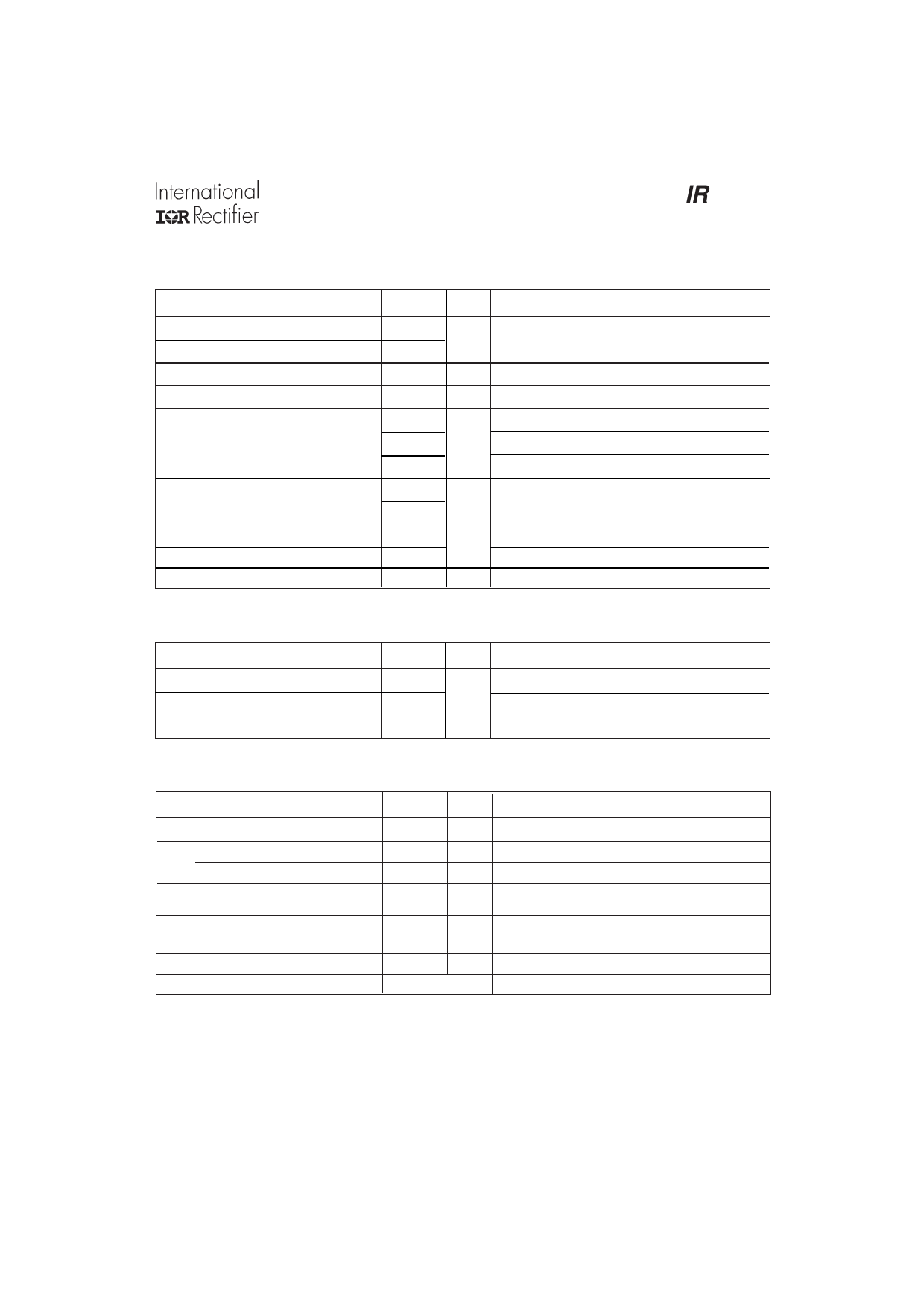
16TTS.. S SAFEIR Series
Bulletin I2105 rev. D 12/98
Triggering
Parameters
PGM Max. peak Gate Power
PG(AV) Max. average Gate Power
+ IGM Max. paek positive Gate Current
- VGM Max. paek negative Gate Voltage
IGT Max. required DC Gate Current
to trigger
VGT Max. required DC Gate Voltage
to trigger
VGD Max. DC Gate Voltage not to trigger
IGD Max. DC Gate Current not to trigger
16TTS..S Units
8.0
W
2.0
1.5
A
10
V
90
mA
60
35
3.0
V
2.0
1.0
0.25
2.0
mA
Conditions
Anode supply = 6V, resistive load, TJ = - 10°C
Anode supply = 6V, resistive load, TJ = 25°C
Anode supply = 6V, resistive load, TJ = 125°C
Anode supply = 6V, resistive load, TJ = - 10°C
Anode supply = 6V, resistive load, TJ = 25°C
Anode supply = 6V, resistive load, TJ = 125°C
TJ = 125°C, VDRM = rated value
TJ = 125°C, VDRM = rated value
Switching
Parameters
tgt Typical turn-on time
trr Typical reverse recovery time
tq Typical turn-off time
16TTS..S Units
0.9
µs
4
110
TJ = 25°C
TJ = 125°C
Conditions
Thermal-Mechanical Specifications
Parameters
16TTS..S Units
Conditions
TJ Max. Junction Temperature Range - 40 to 125 °C
Tstg Max. Storage Temperature Range - 40 to 125 °C
Soldering Temperature
240
°C
for 10 seconds (1.6mm from case)
RthJC Max. Thermal Resistance Junction
to Case
RthJA Typ. Thermal Resistance Junction
to Ambient (PCB Mount)**
wt Approximate Weight
1.3
°C/W DC operation
40
°C/W
2 (0.07) g (oz.)
T Case Style
D2 Pak (SMD-220)
**When mounted on 1" square (650mm2) PCB of FR-4 or G-10 material 4 oz (140µm) copper 40°C/W
For recommended footprint and soldering techniques refer to application note #AN-994
www.irf.com
3
Share Link: 