VSC7130RC(2000) Ver la hoja de datos (PDF) - Vitesse Semiconductor
Número de pieza
componentes Descripción
Fabricante
VSC7130RC
(Rev.:2000)
(Rev.:2000)
Vitesse Semiconductor

VSC7130RC Datasheet PDF : 22 Pages
| |||
VITESSE
SEMICONDUCTOR CORPORATION
Advance Product Information
VSC7130
Dual Repeater/Retimer
for Fibre Channel and Gigabit Ethernet
added/dropped between packets following the rules delineated by the Fibre Channel Specifications mentioned
previously.
Please refer to the “VSC7130 User’s Manual” for more information regarding retimer operation and associ-
ated register controls.
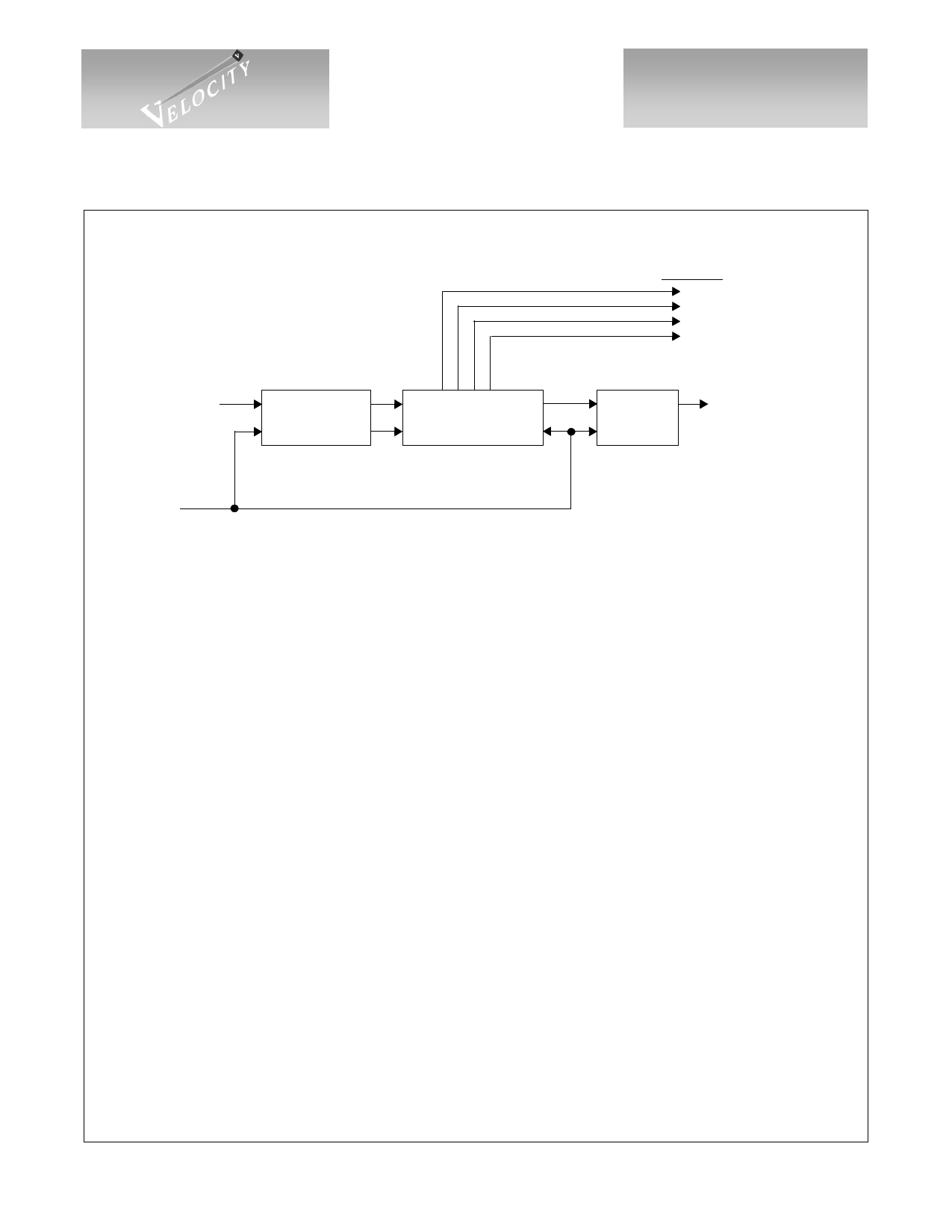
Signal Detection
The receiver, RX1, has an analog signal detect output indicating, when HIGH, that the input contains a
valid Fibre Channel or Gigabit Ethernet signal level. One analog and two digital checks are used to determine if
the incoming signal contains valid data, and combine to form the preliminary signal detect (PSDx) for each
channel:
1.) Analog transition detection is performed on the input to verify that the signal swings are of adequate
amplitude. The RX1+/- input buffer contains a differential voltage comparator which will go high if the differ-
ential peak-to-peak amplitude is greater than 375mV or LOW if under 200mV. If the amplitude is between 200
and 375mV, the output is indeterminate. The RXBIAS input may be adjusted to override these internally set
levels in order to provide either different levels or tighter tolerance. If RXBIAS is left open, these levels are
active. This check only applies to PSD1.
2.) Serial data, after the CDR, is monitored for more than five consecutive zeros or ones. Valid 8B/10B data
will not have a run length greater than 5 clock periods.
3.) Serial data, after the CDR, is monitored for K28.5- (0011111010). Valid Fibre Channel or Gigabit
Ethernet data will contain a K28.5- character during ~64K reference clock period. If a K28.5- is not detected
during the period, SDx will be set LOW for the next period.
Please refer to the “VSC7130 User’s Manual” for a more complete description of the signal detect circuitry
and its associated register controls.
Hub Support
Several functions are provided in the CDRx/SDUx circuitry to support FC-AL Hubs. Two programmable
40-bit registers are available to generate data on TX or SO. This allows simple 40-bit patterns to be generated
easily. Monitoring of the serial data out of the repeater provides the user with information concerning data con-
tent of packets as they are received. Many FC-AL ordered sets are detected (all ARBs, IDLE, all LIPs, all CLS
and all OPENs). Furthermore, two 40-bit registers/comparators are provided to allow the user to identify when
user programmable patterns occur in the data. One use of these would be to monitor for the presence of ordered
sets defined after release of this product.
Please refer to the “VSC7130 User’s Manual” for a more complete description of the ordered set generation
and recognition capabilities and associated register controls.
Performance Monitoring
In order to determine the relative traffic on the link, a 32-bit counter is provided which increments on each
occurrence of an ARB ordered set or an IDLE ordered set. By reading this counter periodically, the relative
traffic on the link can be calculated.
G52297-0, Rev. 2.3
1/17/00
© VITESSE SEMICONDUCTOR CORPORATION
741 Calle Plano, Camarillo, CA 93012 • 805/388-3700 • FAX: 805/987-5896
Page 9
Share Link: