CR0201-FW-1002GLF Ver la hoja de datos (PDF) - Unspecified
Número de pieza
componentes Descripción
Fabricante
CR0201-FW-1002GLF Datasheet PDF : 3 Pages
| |||
*RoHS COMPLIANT
Features
■ Requires 64 % less space than 0402-size
resistor
■ RoHS compliant*
■ Power rating at 70 °C = 1/20 W
■ Three layer termination process with
nickel barrier prevents leaching and
provides excellent solderability
■ Suitable for most types of soldering
processes
■ Standard packaging on paper tape and
reel
CR0201 - Chip Resistor
Electrical Characteristics
Power Rating @ 70 °C ................ 1/20 W
Operating Temperature Range
............................... -55 °C to +125 °C
Derated to 0 Load at .................+125 °C
Maximum Working Voltage..............25 V
Maximum Overload Voltage ............50 V
Resistance Range
1 %, E-96
and E-24 .......10 ohms to 2 megohms
5 %, E-24 ....10 ohms to 10 megohms
Zero Ohm Jumper............<0.05 ohms
Temperature Coefficient
1 % and 5 %................. ±200 ppm/°C
Zero Ohm Jumper......................... N/A
Zero Ohm Jumper
Rated Current..............................0.5 A
Maximum Overload Current ...........1 A
AEC-Q200 ..................... Contact Bourns
to confirm availability
For Standard Values Used in Capacitors,
Inductors, and Resistors, click here.
Part Marking System
No Marking on the CR0201 Chip
Resistors.
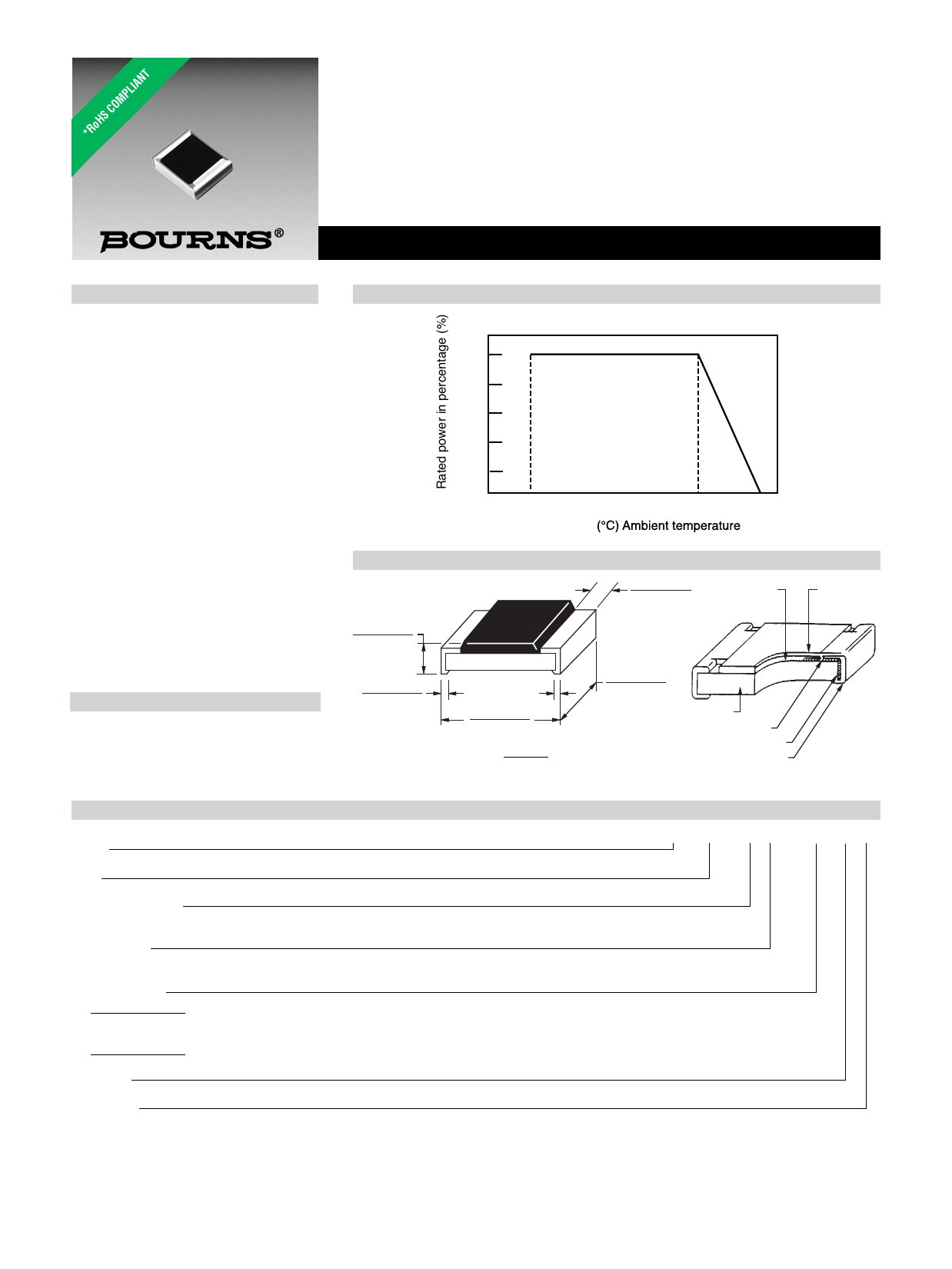
Derating Curve
100
80
60
40
20
0
-55
Dimensional Drawings
0.23 ± 0.03
(0.009 ± 0.001)
0.15 ± 0.05
(0.006 ± 0.002)
0.60 ± 0.03
(0.024 ± 0.001)
DIMENSIONS:
MM
(INCHES)
0
70
125
0.12 ± 0.05
(0.005 ± 0.002)
Resistor (Ru02)
(Jumper chip is
a conductor)
Overcoat
0.30 ± 0.03
(0.012 ± 0.001)
Alumina Substrate
Internal Electrode
Secondary Electrode (Nickel Plated)
External Electrode (Sn)
How to Order
Model
(CR = Chip Resistor)
CR 0201 - F W - 8252 G LF
Size
• 0201
Resistance Tolerance
F = ±1 % .................. For values from 10 ohms through 2 megohms
J = ±5 % ................... For values from 10 ohms through 10 megohms, and for zero ohm jumper
TCR (ppm/°C)
W = ±200 .................. Used with “F” and “J” Resistance Tolerance code for all values except zero ohm jumper
/ = N/A .................... Used with zero ohm jumper only
Resistance Value
For 1 % Tolerance:
<100 ohms ................ “R” designates decimal point (example: 24R3 = 24.3 ohms)
≥100 ohms ................ First three digits are significant, fourth digit represents number of zeros to follow (example: 8252 = 82.5k ohms)
For 5 % Tolerance:
≥10 ohms .................. First two digits are significant, third digit represents number of zeros to follow (example: 474 = 470k ohms; 000 = Jumper)
Packaging
G = Paper Tape (10,000 pcs.) on 7-inch Plastic Reel
Termination
LF = Tin-plated (RoHS compliant)
*RoHS Directive 2002/95/EC Jan. 27, 2003 including annex and RoHS Recast 2011/65/EU June 8, 2011.
Specifications are subject to change without notice.
The device characteristics and parameters in this data sheet can and do vary in different applications and actual device performance may vary over time.
Users should verify actual device performance in their specific applications.
Share Link: 