DS2406P Ver la hoja de datos (PDF) - Dallas Semiconductor -> Maxim Integrated
Número de pieza
componentes Descripción
Fabricante
DS2406P Datasheet PDF : 30 Pages
| |||
DS2406
OVERVIEW
The block diagram in Figure 1 shows the relationships between the major control and memory sections of
the DS2406. The device has four major data components: 64-bit lasered ROM, 1024 bits of EPROM data
memory, status memory, and the PIO-control block. The hierarchical structure of the 1-Wire protocol is
shown in Figure 2. The bus master must first provide one of the five ROM function commands: Read
ROM, Match ROM, Search ROM, Skip ROM, or Conditional Search ROM. The protocol required for
these ROM functions is described in Figure 13. After a ROM functions command is successfully
executed, the PIO-control and memory functions become accessible and the master may provide any one
of the six memory- and control function commands. The protocol for these functions is described in
Figure 7. All data is read and written least significant bit first.
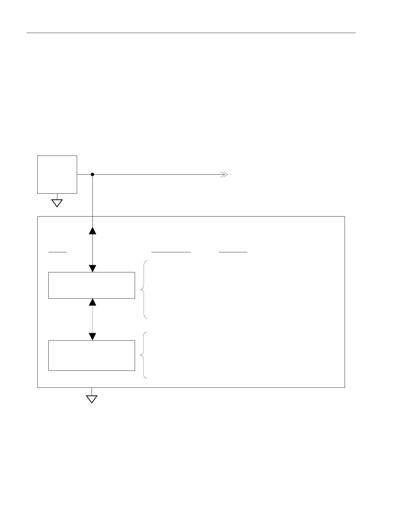
HIERARCHICAL STRUCTURE FOR 1-Wire PROTOCOL Figure 2
Bus
Master
1-Wire Bus
Other
Devices
Command
Level
1-Wire ROM Function
Commands (see Figure 13)
DS2406
Available
Commands
Read ROM
Match ROM
Search ROM
Skip ROM
Conditional
Search ROM
Data Fields
Affected
64-bit ROM
64-bit ROM
64-bit ROM
N/A
64-bit ROM,
Conditional Search Settings
at Status Memory Location 7,
Device/Channel Status
DS2406 specific
Memory Function
Commands (see Figure 7)
Write Memory
Write Status
Read Memory
Read Status
Ext. Read Memory
Channel Access
1024-bit EPROM
Status Memory
1024-bit EPROM
Status Memory
1024-bit EPROM
PIO Channels
3 of 30
Share Link: 