LA76931 Ver la hoja de datos (PDF) - Unspecified
Número de pieza
componentes Descripción
Fabricante
LA76931 Datasheet PDF : 74 Pages
| |||
3
CHAPTER ONE Power Supply
TV require a variety of voltage ( at various power levels) to work normally. The function of the voltage power supply is to
take the AC line input and produce various DC voltages. In all case , the power to the horizontal output transistor (HOT)
of the horizontal deflection system is obtained directly from the DC voltage power supply. In the power design of LA 76931
series , there is a separate switch mode power supply that provides all of the DC voltage.
There will be always be :
A. A power switch . It enable to turn on or off the main power.
B. A set of rectifiers - in a bridge configuration - to turn the AC into DC. Small ceramic capacitors are place across the
diodes to reduce RF interference.
C. One large filter capacitor to smooth the unregulated DC. In countries with 220 -240VAC power , it will typically be around
400V DC.
D. In TV , it need switching typical power to provide stable DC .
E. A degauss control circuit including a Posistor ( a combination of heater disk and Positive Temperature Coefficient (PTC)
thermistor in a single package). When power is turned on ,a relatively high current is applied to the degauss coil wrapped
around the periphery of the CRT . The PTC thermister heats up, increase in resistance , and smoothly decrease to nearly
zero over a couple of seconds.
F. A standby power supply for the microcontroller and remote sensor. It derives from the DC voltage power supply.
Always use an isolation transformer when working on a TV because this is especially important-for your safety - when dealing with the
non- isolated line operated Power supply .
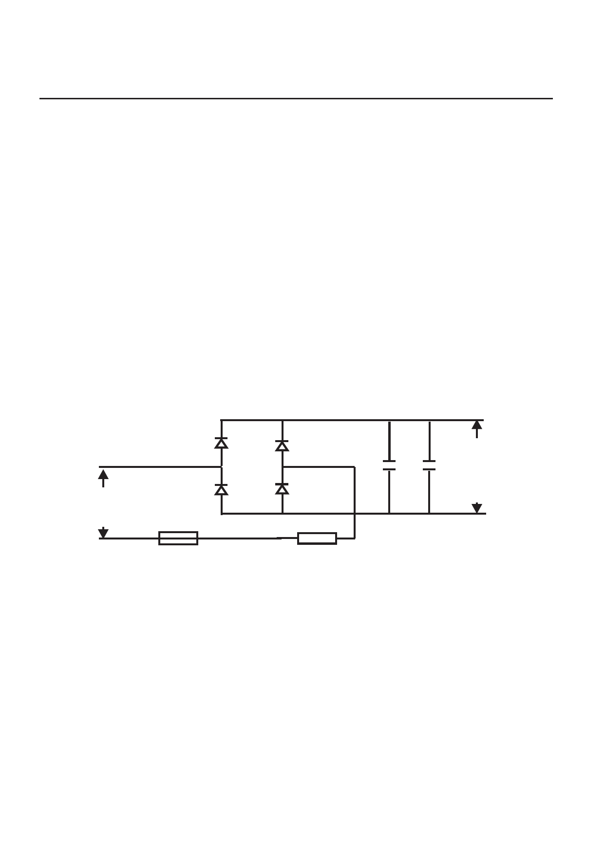
1.1 Typical power rectifier
The partial schematicbelow is foundedin the LA76931 series TV, some partsare not shownincluding the powerswitch, bypass capacitors
across the rectifie diodes (C503-C506)and the RFI line filter(L501,L502).
VD 503
RM 11C
AC 220-240V IN
VD 504
RM 11C
Fu501
T2.5A 250V
VD 505
RM 11C
VD 506
RM 11C
R502
3R 9
+
+
DC 300V OUT
-
-
C507
C518
150u/400V 1nF/1kv
The line fuse F501 is typically 2.5A, usually a normal fast blow type . Even so, it may not blow as a result of faults down
the line - the fusable resistor or regulator may fail first. The main bridge rectifier is composed of 4 discrete diodes(VD503-VD506)
but may also be a single unite. Failures - usually shorted diodes-are common. The main filter capacitor (C507) is very important .
A typical TV continue to work at normal line voltage without any noticeable degra-dation in performance( hum bars, hum in sound
or shutdown) even if this capacitor is reduced in value by 75%. Its value is therefore not critical.
Share Link: 