HMC292(V02) Ver la hoja de datos (PDF) - Hittite Microwave
Número de pieza
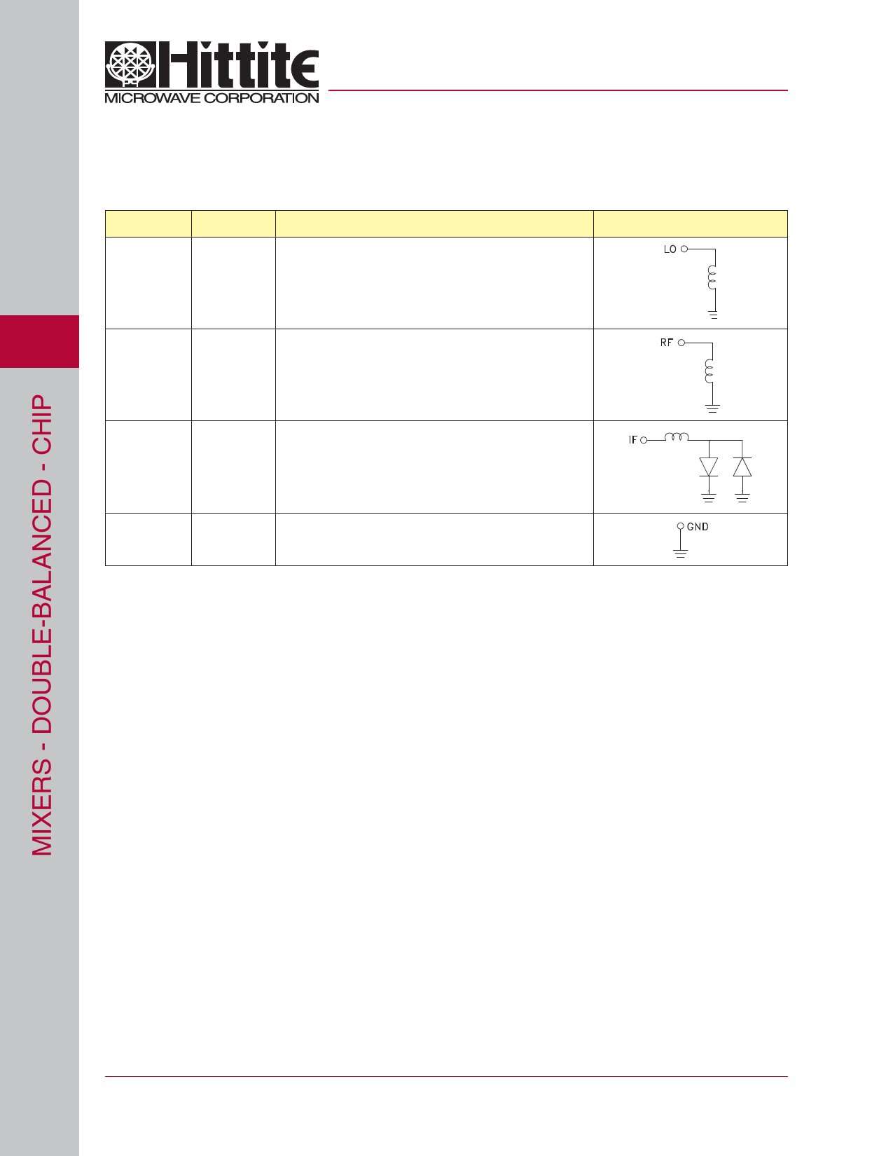
componentes Descripción
Fabricante
HMC292 Datasheet PDF : 6 Pages
| |||
v02.1202
MICROWAVE CORPORATION
HMC292
GaAs MMIC DOUBLE-BALANCED
MIXER, 18 - 32 GHz
MMIC Assembly Techniques
Ribbon Bond
Ribbon Bond
5
Mounting & Bonding Techniques for Millimeterwave GaAs MMICs
The die should be attached directly to the ground plane eutectically or with conductive epoxy (see HMC general Handling, Mounting,
Bonding Note).
50 Ohm Microstrip transmission lines on 0.127mm (5 mil) thick alumina thin film substrates are recommended for bringing RF to and
from the chip (Figure 1). If 0.254mm (10 mil) thick alumina thin film substrates must be used, the die should be raised 0.150mm (6
mils) so that the surface of the die is coplanar with the surface of the substrate. One way to accomplish this is to attach the 0.102mm (4
mil) thick die to a 0.150mm (6 mil) thick molybdenum heat spreader (moly-tab) which is then attached to the ground plane (Figure 2).
Microstrip substrates should be brought as close to the die as possible in order to minimize bond wire length. Typical die-to-substrate
spacing is 0.076mm (3 mils). Gold ribbon of 0.076 mm x 0.013 mm (3 mil x 0.5 mil) of minimal length <0.31 mm (<12 mils) is recom-
mended to minimize inductance on the RF ports.
5 - 74
For price, delivery, and to place orders, please contact Hittite Microwave Corporation:
12 Elizabeth Drive, Chelmsford, MA 01824 Phone: 978-250-3343 Fax: 978-250-3373
Order Online at www.hittite.com
Share Link: 