ZPSD211RN Ver la hoja de datos (PDF) - STMicroelectronics
Número de pieza
componentes Descripción
Fabricante
ZPSD211RN Datasheet PDF : 51 Pages
| |||
PSD211R Family
7.0
ZPSD
Background
(Cont.)
7.1 Integrated Power Management TM Operation
Upon each address or logic input change to the ZPSD, the device powers up from low
power standby for a short time. Then the ZPSD consumes only the necessary power to
deliver new logic or memory data to its outputs as a response to the input change. After the
new outputs are stable, the ZPSD latches them and automatically reverts back to standby
mode. The ICC current flowing during standby mode and during DC operation is identical
and is only a few microamperes.
The ZPSD automatically reduces its DC current drain to these low levels and does not
require controlling by the CSI (Chip Select Input). Disabling the CSI pin unconditionally
forces the ZPSD to standby mode independent of other input transitions. The only
significant power consumption in the ZPSD occurs during AC operation. The ZPSD
contains the first architecture to apply Zero-power techniques to memory and logic blocks.
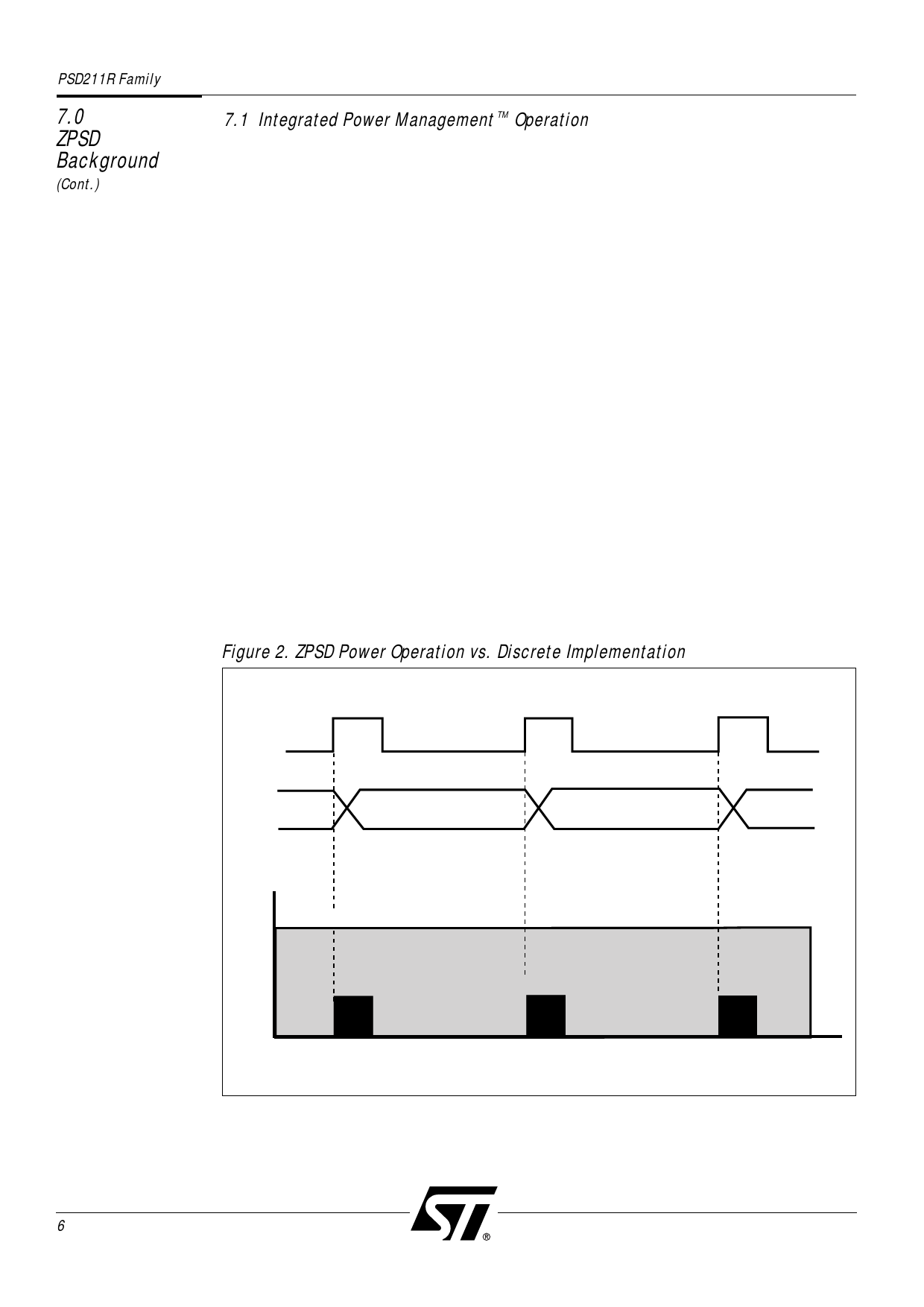
Figure 2 compares ZPSD zero power operation to the operation of a discrete solution.
A standard microcontroller (MCU) bus cycle usually starts with an ALE (or AS) pulse and
the generation of an address. The ZPSD detects the address transition and powers up for a
short time. The ZPSD then latches the outputs of the PAD and EPROM to the new values.
After finishing these operations, the ZPSD shuts off its internal power, entering standby
mode. The time taken for the entire cycle is less than the ZPSD’s “access time.”
The ZPSD will stay in standby mode while its inputs are not changing between bus
cycles. In an alternate system implementation using discrete EPROM, and other discrete
components, the system will consume operating power during the entire bus cycle.
This is because the chip select inputs on the memory devices are usually active throughout
the entire cycle. The AC power consumption of the ZPSD may be calculated using the
composite frequency of the MCU address and control signals, as well as any other logic
inputs to the ZPSD.
Figure 2. ZPSD Power Operation vs. Discrete Implementation
ALE
ADDRESS
EPROM
ACCESS
EPROM
ACCESS
EPROM
ACCESS
DISCRETE EPROM & LOGIC
ICC
ZPSD
ZPSD
TIME
ZPSD
6
Share Link: 