SAA7128H Ver la hoja de datos (PDF) - Philips Electronics
Número de pieza
componentes Descripción
Fabricante
SAA7128H Datasheet PDF : 56 Pages
| |||
Philips Semiconductors
Digital video encoder
Product specification
SAA7128H; SAA7129H
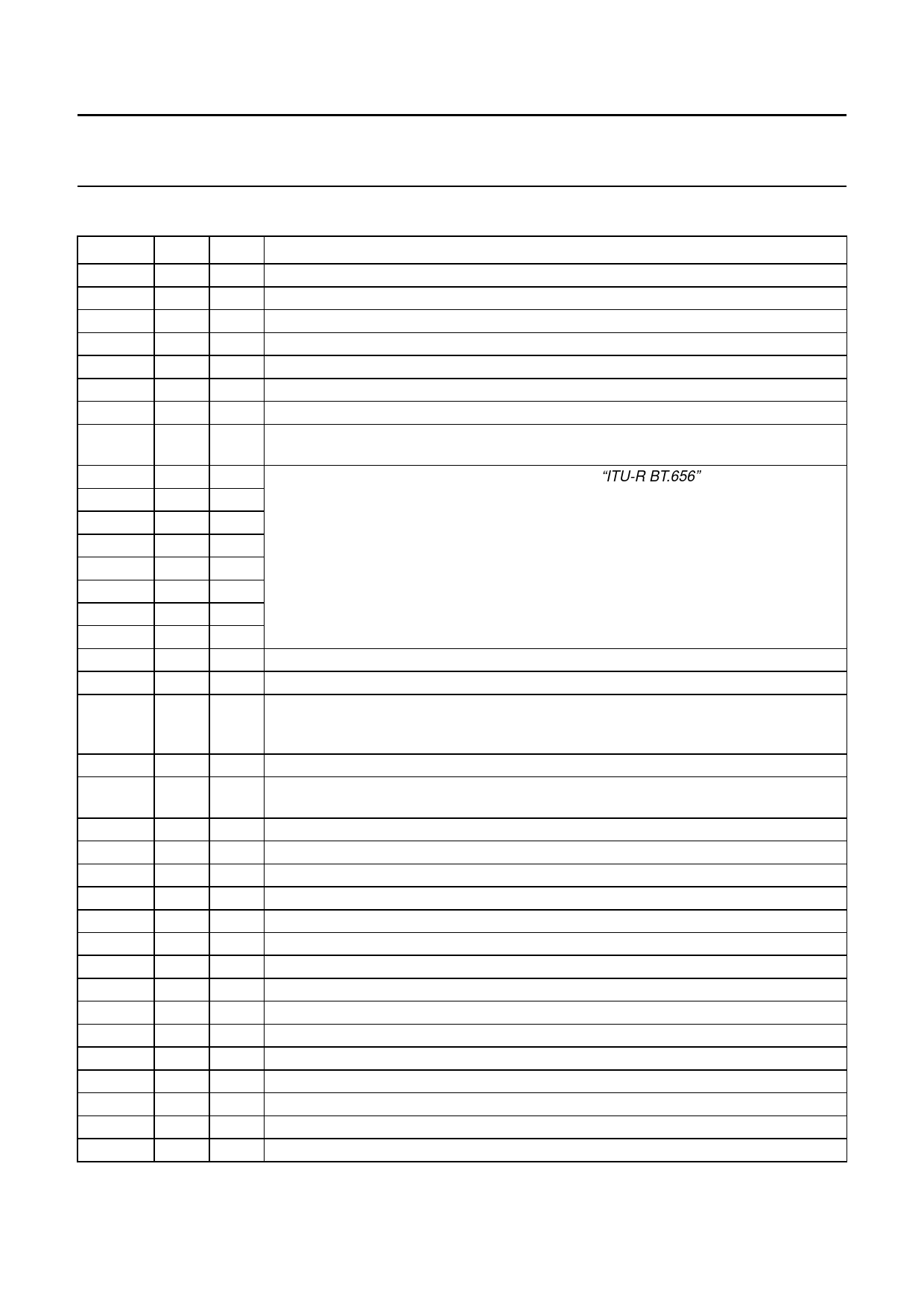
6 PINNING
SYMBOL PIN TYPE
DESCRIPTION
RES
1−
reserved pin; do not connect
SP
2I
test pin; connected to digital ground for normal operation
AP
3I
test pin; connected to digital ground for normal operation
LLC1
4I
line-locked clock input; this is the 27 MHz master clock
VSSD1
VDDD1
RCV1
5 supply digital ground 1
6 supply digital supply voltage 1
7 I/O raster control 1 for video port; this pin receives/provides a VS/FS/FSEQ signal
RCV2
8 I/O
raster control 2 for video port; this pin provides an HS pulse of programmable length or
receives an HS pulse
MP7
MP6
MP5
MP4
9I
10 I
11 I
12 I
double-speed 54 MHz MPEG port; it is an input for “ITU-R BT.656” style multiplexed
CB-Y-CR data; data is sampled on the rising and falling clock edge; data sampled on the
rising edge is then sent to the encoding part of the device; data sampled on the falling
edge is sent to the RGB part of the device (or vice versa, depending on programming)
MP3
13 I
MP2
14 I
MP1
15 I
MP0
16 I
VDDD2
VSSD2
RTCI
VDD(I2C)
SA
17 supply digital supply voltage 2
18 supply digital ground 2
19 I
real-time control input; if the LLC1 clock is provided by an SAA7111 or SAA7151B, RTCI
should be connected to the RTCO pin of the respective decoder to improve the signal
quality
20 supply sense input for I2C-bus voltage; connect to I2C-bus supply
21 I
select I2C-bus address; LOW selects slave address 88H, HIGH selects slave address
8CH
VSSA1
RED
C
22 supply analog ground 1 for RED (CR), C (CVBS) and GREEN (Y) outputs
23 O
analog output of RED (CR) signal
24 O
analog output of chrominance (CVBS) signal
VDDA1
GREEN
25 supply analog supply voltage 1 for RED (CR) and C (CVBS) outputs
26 O
analog output of GREEN (Y) signal
VBS
27 O
analog output of VBS (CVBS) signal
VDDA2
BLUE
CVBS
28 supply analog supply voltage 2 for VBS (CVBS) and GREEN (Y) outputs
29 O
analog output of BLUE (CB) signal
30 O
analog output of CVBS (CSYNC) signal
VDDA3
VSSA2
VSSA3
XTALO
31 supply analog supply voltage 3 for BLUE (CB) and CVBS (CSYNC) outputs
32 supply analog ground 2 for VBS (CVBS), BLUE (CB) and CVBS (CSYNC) outputs
33 supply analog ground 3 for the DAC reference ladder and the oscillator
34 O
crystal oscillator output
XTALI
35 I
crystal oscillator input; if the oscillator is not used, this pin should be connected to ground
VDDA4
36 supply analog supply voltage 4 for the DAC reference ladder and the oscillator
2000 Mar 08
6
Share Link: 