HSP50306(2004) Ver la hoja de datos (PDF) - Intersil
Número de pieza
componentes Descripción
Fabricante
HSP50306 Datasheet PDF : 8 Pages
| |||
HSP50306
The Block Diagram of the QPSK Demodulator is shown on
page 1. To demodulate the data, the I.F. samples are multi-
plied by sine and cosine samples from a numerically con-
trolled oscillator. The digital mixer outputs are then low pass
filtered to remove mixer products. The filtered data is then
equalized by a 4 tap equalizer (1 precursor, one reference
tap, and a 2 tap Decision Feedback Equalizer (DFE) to
remove distortion caused by multipath. The output of the
equalizer is differentially decoded and multiplexed into the
output data stream. The carrier tracking loop providing the
L.O. for the digital mixer is a second order digital Costas loop
with a tracking bandwidth of ~10kHz. A sweep circuit
searches the carrier uncertainty using a triangle sweep algo-
rithm during acquisition. A lock detector controls the sweep
and indicates when valid data is available. The recovered
data rate clock is generated by another numerically controlled
oscillator. The timing recovery loop is a first order decision
directed digital phase locked with a loop bandwidth of ~3kHz.
The Level Detect circuitry generates the AGC error signal by
rectifying the I.F. input samples and comparing them against
a threshold. The error signal is low if the signal magnitude is
above the upper threshold, high if the magnitude is below the
lower limit.
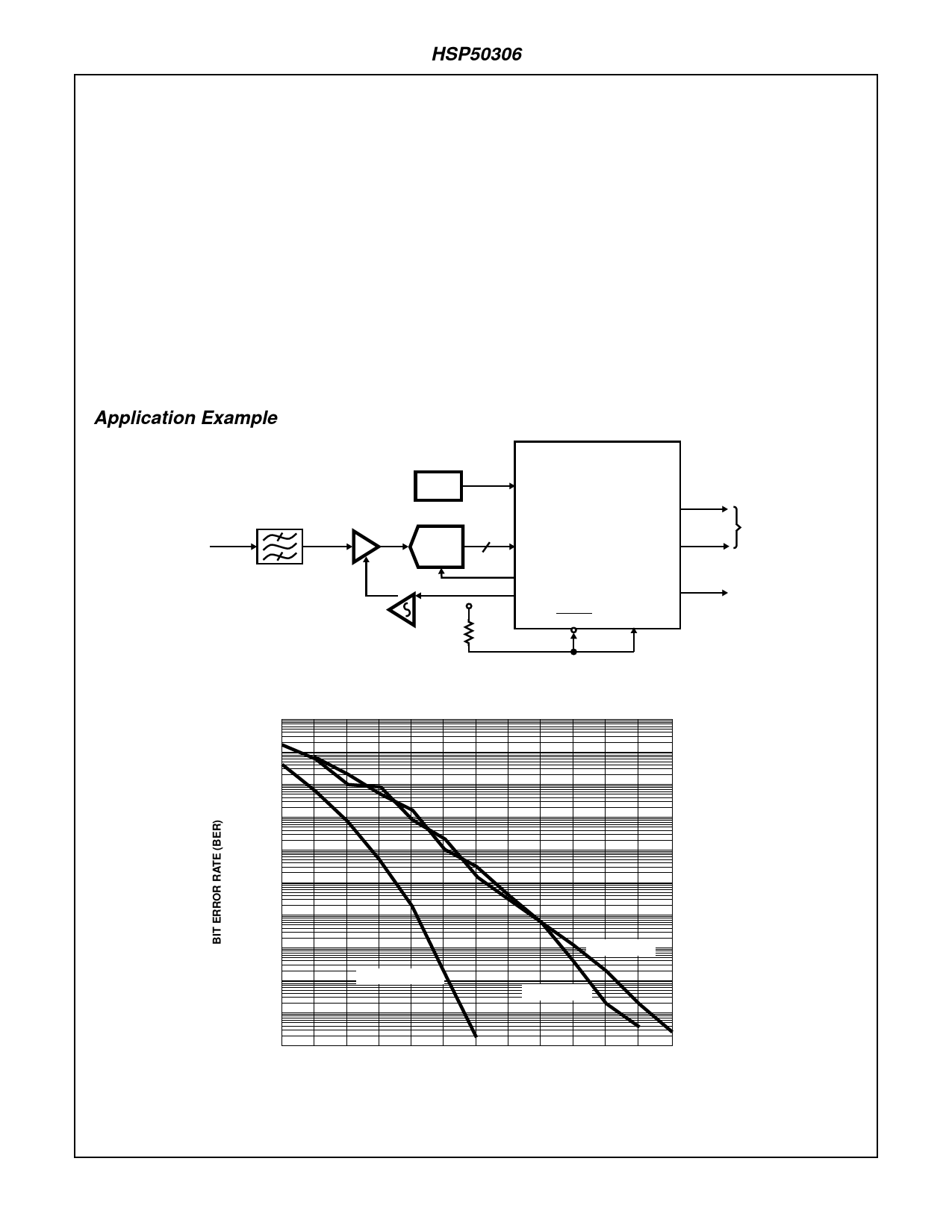
Figure 1 shows the circuit of a typical demodulator application.
The typical Bit Error Rate (BER) performance is shown in
Figure 2 for both 4-bit and 6-bit quantized inputs. The
theoretical QPSK BER Performance Curve is provided for
reference. Note that the BER performance shown in Figure 2
includes a multipath distortion element at the input, in addition
to the desired signal. This multipath distortion is
representative of receive signal distortions found in cable data
links.
Table 1 details the BER, Acquisition and Delay Performance
Specifications of the HSP50306 QPSK demodulator chip,
based on an input that complies with the specifications
detailed in Table 2.
Application Example
DIGITIZED
10.7MHz (2.1MHz)
IF INPUT
I.F. FILTER
(25.6MHz)
26.97MHz
OSC
CA3304/6
6
A/D
V+
HSP50306
CLKIN
CLKOUT
DIN0-5
ADCLK
AGCOUT
RESET
DATAOUT
LOCK
TEST
2.048 MBPS
OUTPUT
DATA/CLK
FIGURE 1. APPLICATIONS CIRCUIT EXAMPLE
0.01
0.001
0.0001
0.00001
1E-06
1E-07
1E-08
1E-09
1E-10
1E-11
THEORETICAL
4-BIT DATA
6-BIT DATA
1E-12
11 12 13 14 15 16 17 18 19 20 21 22 23
ES / NO
NOTE: Simulation performed using alpha = 0.4 Root Raised Cosine Transmit Filtering, Multipath -10dBc at 72° at 1.6µs.
FIGURE 2. TYPICAL BIT ERROR RATE PERFORMANCE
3
Share Link: 