HSP50016 Ver la hoja de datos (PDF) - Intersil
Número de pieza
componentes Descripción
Fabricante
HSP50016 Datasheet PDF : 31 Pages
| |||
HSP50016
+90o
STARTING PHASE
θMAX INCR
-4θ∆
(5)
(0)
θMAX INCR
(4)
±180o -3θ∆
(3)
θMAX INCR
-2θ∆
(1)
(2)
-90o
θMAX INCR
-θ∆
θOFFSET
0o
θMAX INCR
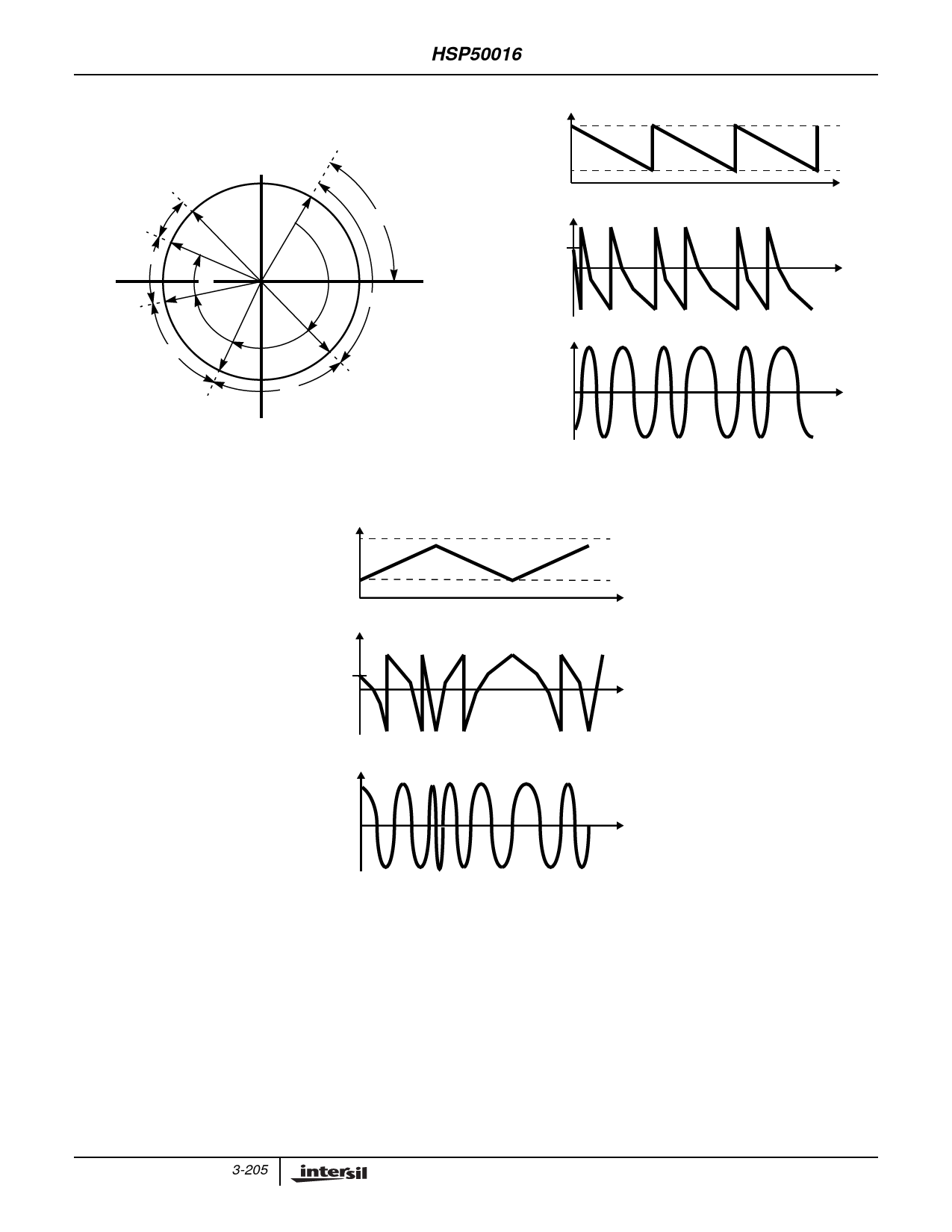
FIGURE 5A. PHASE WORD DURING DOWN CHIRP
PHASE INCREMENT
MAXIMUM
MINIMUM
PHASE WORD
PHASE
OFFSET
COSINE OUTPUT OF SIN/COS GENERATOR
FIGURE 5B. DOWN CHIRP
PHASE INCREMENT
MAXIMUM
MINIMUM
PHASE WORD
PHASE
OFFSET
COSINE OUTPUT OF SIN/COS GENERATOR
TIME
TIME
TIME
TIME
TIME
TIME
FIGURE 6. UP/DOWN CHIRP
In Up/down Chirp Mode, the phase accumulator is set to the
phase offset value and the minimum phase increment is
loaded into the Phase Increment Register. The delta phase
increment is added to the 24 LSBs of the Phase Increment
Register to form a new phase increment at each clock. The
phase increment is allowed to grow until it nears the
maximum phase increment value (as defined in the up chirp
description). The delta phase increment value is then
subtracted from the least significant bits of the Phase
Increment Register to form a new phase increment at each
clock. The phase increment is allowed to diminish until it
reaches the minimum phase increment value (as defined in
the down chirp description). The Phase Increment Register
is then reloaded with the minimum phase increment, and the
up/down cycle begins again. See Figure 6 for a graphical
representation of this process.
The minimum and maximum phase increments have
allowable values from 0 to 232-1. This corresponds to the
phase increment:
0 < Phase Increment < π(1 – 2–32) radians
(EQ. 4)
3-205
Share Link: 